Propeller Message Display with Temperature Indicator
In this project, we will present a propeller display that is controlled by a microcontroller and can show any message that is provided to it through the hyper- terminal of a personal comp…
Know the mission before touching a wire.
Understand what you are making, prepare the right tools, and make the workbench safe.
Project details
Propeller Message Display with Temperature Indicator is a electronics project. In this project, we will present a propeller display that is controlled by a microcontroller and can show any message that is provided to it through the hyper- terminal of a personal comp…
- Source pages
- 257-260
- Named parts
- 3
- Build goal
- Working, tested prototype
Tools you need
- Digital multimeter
- Wire stripper and side cutters
- Soldering iron with a fine tip
- Current-limited bench supply
Use eye protection, good lighting, and a clean insulated surface throughout the build.
Safety precautions
- Disconnect every power source before changing a connection.
- Check component polarity, pinout, and supply voltage twice.
- Use a current limit for the first power-up.
- Keep liquids, loose metal, and uninsulated wires away from the bench.
Gather, identify, and understand every part.
Use the standardized inventory, then open What's this? to learn each part's role, advantages, limitations, handling, and specifications.
What's this?Image, role, pros, cons, handling & specifications
Temperature sensor
A sensor converts a physical condition into an electrical signal the circuit can measure.
What it does hereIt provides project input as an analogue, digital, resistive, frequency, or calibrated signal.
Buy / compare this part ↗Advantages
- Adds real-world awareness
- Can usually be tested independently
- Often supports calibration
Limitations
- Readings can drift
- Placement affects results
- Some sensors need warm-up or calibration
Handling
- Protect the sensing surface
- Observe supply voltage and polarity
- Keep signal leads away from noisy power wiring
Specifications to verify
- Use the exact model, value, package, and rating listed for Temperature sensor; similar-looking parts are not always interchangeable.
- Confirm supply range, output type, measurement range, accuracy, response time, and pin order.
What's this?Image, role, pros, cons, handling & specifications
MAX232
A named project component whose exact role is defined by the source circuit and build guide.
What it does hereIt performs a documented electrical, control, interface, or construction function in this project.
Buy / compare this part ↗Advantages
- Selected for this project
- Can be checked independently
- Supports modular troubleshooting
Limitations
- Substitutes may differ
- Generic names can hide variants
- Pinouts and ratings vary
Handling
- Compare the received part with the source
- Keep it labelled
- Do not force connectors or adjusters
Specifications to verify
- Use the exact model, value, package, and rating listed for MAX232; similar-looking parts are not always interchangeable.
- Confirm dimensions, ratings, connection method, polarity, and environmental limits.
What's this?Image, role, pros, cons, handling & specifications
LED1, LED8 - indicator LEDs identified in the circuit
A named project component whose exact role is defined by the source circuit and build guide.
What it does hereIt performs a documented electrical, control, interface, or construction function in this project.
Buy / compare this part ↗Advantages
- Selected for this project
- Can be checked independently
- Supports modular troubleshooting
Limitations
- Substitutes may differ
- Generic names can hide variants
- Pinouts and ratings vary
Handling
- Compare the received part with the source
- Keep it labelled
- Do not force connectors or adjusters
Specifications to verify
- Use the exact model, value, package, and rating listed for LED1, LED8 - indicator LEDs identified in the circuit; similar-looking parts are not always interchangeable.
- Confirm dimensions, ratings, connection method, polarity, and environmental limits.
Connect one verified path at a time.
Explore the named components and standardized signal flow, then use Source Check to verify exact physical pins, values, and topology before applying power.
Trace this circuit.
Propeller Message Display with Temperature Indicator: interactive parts, standardized terminals, responsive anchored wires, student explanations, and the original circuit reference in one shared system.
Trace before wiring
Follow power, ground, inputs, processing, and outputs in that order. Never guess a pin from package shape alone.
Connect with power off
Make short, labelled connections and share a common ground only where the schematic requires it.
Inspect every joint
Check continuity, polarity, adjacent shorts, and loose connections before the first power-up.
Open all source diagrams and build views 2 visuals
Confirm the hardware-only control path.
This project does not include firmware in the source. The circuit itself provides the required behaviour.
How to connect
- Match every controller label to the circuit view and source pin map.
- Join grounds before signal wires when separate low-voltage supplies are used.
- Keep motors, relays, pumps, and other loads on a suitable driver and external supply.
Common mistakes
Reversed VCC/GND, board-label versus GPIO-number confusion, missing common ground, and charge-only USB cables.
Troubleshoot
Disconnect loads, continuity-test one path at a time, then test with a current limit.
Software preparation
No IDE, board package, library, or firmware upload is required for this project.
If you add a programmable controller as an extension, document its pin map separately.
How to upload code
The original design is implemented entirely in hardware, so proceed after verifying the circuit and supply.
Assemble, deploy, test, and troubleshoot.
Use the complete source notes in build order, then pass the final checks before calling the project finished.
Build in functional stages
- Power and regulation
- Controller or processing stage
- Inputs and sensors
- Outputs and loads
- Enclosure and strain relief
Power up safely
- Inspect unpowered continuity first
- Apply the lowest safe current limit
- Measure supply rails before signals
- Add one load at a time
- Record expected and actual results
Work from simple to complex
- Confirm power, ground, polarity, and orientation
- Compare each pin with the source
- Test inputs separately from outputs
- Replace only one variable at a time
- Power off before every correction
Follow the documented instructions.
These notes come from this project's source and remain in their original order.
Project overview
Project build noteIn this project, we will present a propeller display that is controlled by a microcontroller and can show any message that is provided to it through the hyper- terminal of a personal computer. In addition, a temperature detecting integrated circuit, model number TMP125, is installed into the propeller display so that the temperature can be displayed in real time. Using only eight LEDs, it displays many characters in a rotating circular route and provides a view that encompasses the whole 360 degrees. It is a dynamic method of display that is both cost-effective and beautiful, and it decreases the complexity of the system overall while simultaneously improving its energy efficiency. A display that faces vertically and has a viewing angle of a full 360 degrees is the primary selling point of this idea.
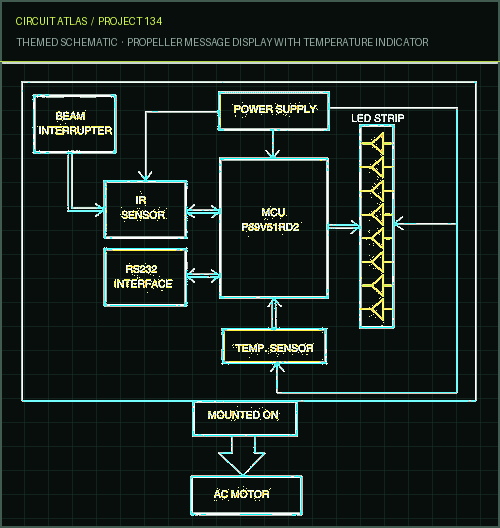
Fig. 1: Block diagram of the propeller message display with temperature indicator The idea that "persistence of vision" should be the driving force behind this endeavor was inspired by that phrase. This phenomenon is connected to the visual capabilities of the human eye, where it is believed that an afterimage can last for about one-quarter of a second. Therefore, if an image is observed at a rate of 25 times per second, it will appear as though it is one continuous picture to the observer. Because of the rapid movement of the LED strip in this display, it is possible to make out a matrix of LEDs. In order to display a variety of characters, the duration of a single revolution is broken up into multiple shorter time periods, each of which is dedicated to controlling whether or not a specific LED is lit. The SPI bus is used to communicate the temperature readings from the temperature IC to the controller. The temperature indication is depicted as a block diagram in figure 1, which illustrates the propeller display. The LED strip is positioned vertically in such a way that when
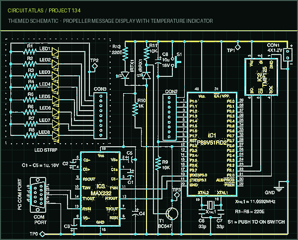
the motor rotates, the strip likewise revolves in a circular form, so providing a display that is visible from all 360 degrees. The RS232 interface, which is being controlled by hyper-terminal, is used to send the message that will be displayed. The message appears on the display for a period of thirty seconds, after which it is replaced by the current temperature, which is taken from the sensor that measures temperature. The IR sensor-beam interrupter assembly is responsible for the generation of interruptions. Circuit and working Fig. 2: Circuit of the propeller message display with temperature indicator The circuit for the propeller display is illustrated in figure 2. The microcontroller P89V51RD2 (IC1), the temperature sensor TMP125 (IC2), the MAX232 (IC3), and a few discrete components are the building blocks for this design. The port pins P1.0 through P1.7 are linked to CON2, which also needs to have a connection made to CON3 of the LED strip, which contains LED1 through LED8. When turned at a high speed, these LEDs come together to form a circular display. Microcontroller. The microcontroller P89V51RD2 is the most important component of the system. The P89V51RD2 is an 8-bit 80C51 microcontroller with 64kB Flash and
1024 bytes of data RAM. It has four 8-bit input/output (I/O) ports, three 16-bit timers and counters, a programmable watchdog timer, eight interrupt sources with four priority levels, enhanced UART and serial peripheral interface (SPI), programmable counter array with PWM and capture/compare functions, and enhanced serial peripheral interface (SPI). It operates up to a 40 MHz crystal and features an oscillator and clock circuits integrated directly onto the device. It is possible to switch between 12 clocks every machine cycle, which is the default setting, and 6 clocks per machine cycle, which can be done through the software. Programming in parallel and in serial fashion can both be done in the Flash program memory. The combination of the resistor R9 and the capacitor C8 is what provides the power-on reset function. The manual reset procedure is accessed through switch S1. The microcontroller receives its fundamental clock frequency from a combination of an 11.0592MHz crystal (XTAL1) and two capacitors with a value of 33pF each (C6 and C7). A sensor of temperature that has a digital output. The TMP125 is a temperature sensor that is compatible with the SPI protocol and is available in a very small SOT23-6 packaging. It is able to measure temperatures with an accuracy of 2 degrees Celsius over a temperature range of 25 degrees Celsius to +85 degrees Celsius and with an accuracy of 2.5 degrees Celsius over a temperature range of 40 degrees Celsius to +125 degrees Celsius. It does not require any external components. TMP125 is a suitable contender for low-power applications due to its low supply current and wide supply voltage range, which ranges from 2.7 V to 5.5 V. TMP125 is an excellent choice for extended thermal monitoring in a wide variety of applications, including those involving communication, computers, consumers, the environment, industrial processes, and instrumentation. In order to interface the temperature sensor, port pins P2.0 through P2.2 of IC1 are utilized.
You built Propeller Message Display with Temperature Indicator.
You followed the full workflow from understanding the mission to testing the finished project. That is a real engineering achievement - well done.
Low Power Voltage Doubler
Ready to reuse what you learned in another project from the same track?
Start this project →