Robot Snake based on Arduino controlled by Android
Twelve servo motors drive the snake's segments, which are joined with metal brackets. A 7.4-volt battery pack powers the servos and controls them with an Arduino Mega. An android app can…
Know the mission before touching a wire.
Understand what you are making, prepare the right tools, and make the workbench safe.
Project details
Robot Snake based on Arduino controlled by Android is a arduino project. Twelve servo motors drive the snake's segments, which are joined with metal brackets. A 7.4-volt battery pack powers the servos and controls them with an Arduino Mega. An android app can…
- Source pages
- 594-596
- Named parts
- 16
- Build goal
- Working, tested prototype
Tools you need
- Digital multimeter
- Wire stripper and side cutters
- Soldering iron with a fine tip
- Current-limited bench supply
- Computer with a data-capable USB cable
Use eye protection, good lighting, and a clean insulated surface throughout the build.
Safety precautions
- Disconnect every power source before changing a connection.
- Check component polarity, pinout, and supply voltage twice.
- Use a current limit for the first power-up.
- Keep liquids, loose metal, and uninsulated wires away from the bench.
Gather, identify, and understand every part.
Use the standardized inventory, then open What's this? to learn each part's role, advantages, limitations, handling, and specifications.
What's this?Image, role, pros, cons, handling & specifications
Arduino Mega 2560
A programmable controller that reads inputs, makes decisions, and drives the project's outputs.
What it does hereIt is the control centre and must use the documented board, pin map, supply, and logic level.
Buy / compare this part ↗Advantages
- Reprogrammable and reusable
- Large learning ecosystem
- Complex behaviour remains changeable
Limitations
- GPIO voltage and current are limited
- Some pins affect boot or communication
- Loads normally need a driver
Handling
- Disconnect power before rewiring
- Avoid static discharge
- Never power motors, relays, or pumps directly from GPIO
Specifications to verify
- Use the exact model, value, package, and rating listed for Arduino Mega 2560; similar-looking parts are not always interchangeable.
- Confirm operating voltage, logic level, pinout, memory, USB interface, and maximum GPIO current.
What's this?Image, role, pros, cons, handling & specifications
12 x 5-6 V positional hobby servo motors sized for the segment brackets
An output component turns an electrical control signal into light, sound, motion, switching, or displayed information.
What it does hereIt presents the circuit result or acts on the physical world.
Buy / compare this part ↗Advantages
- Makes system state visible
- Can be tested separately
- Supports clear troubleshooting
Limitations
- Loads may exceed controller current
- Polarity or driver direction can matter
- Inductive loads create voltage spikes
Handling
- Use the documented driver stage
- Check polarity and load current
- Add flyback protection for inductive loads
Specifications to verify
- Use the exact model, value, package, and rating listed for 12 x 5-6 V positional hobby servo motors sized for the segment brackets; similar-looking parts are not always interchangeable.
- Confirm voltage, current, polarity, interface, driver requirements, and duty cycle.
What's this?Image, role, pros, cons, handling & specifications
HC-05 or HC-06 Bluetooth serial module
A named project component whose exact role is defined by the source circuit and build guide.
What it does hereIt performs a documented electrical, control, interface, or construction function in this project.
Buy / compare this part ↗Advantages
- Selected for this project
- Can be checked independently
- Supports modular troubleshooting
Limitations
- Substitutes may differ
- Generic names can hide variants
- Pinouts and ratings vary
Handling
- Compare the received part with the source
- Keep it labelled
- Do not force connectors or adjusters
Specifications to verify
- Use the exact model, value, package, and rating listed for HC-05 or HC-06 Bluetooth serial module; similar-looking parts are not always interchangeable.
- Confirm dimensions, ratings, connection method, polarity, and environmental limits.
What's this?Image, role, pros, cons, handling & specifications
Digital infrared obstacle-sensor module
A sensor converts a physical condition into an electrical signal the circuit can measure.
What it does hereIt provides project input as an analogue, digital, resistive, frequency, or calibrated signal.
Buy / compare this part ↗Advantages
- Adds real-world awareness
- Can usually be tested independently
- Often supports calibration
Limitations
- Readings can drift
- Placement affects results
- Some sensors need warm-up or calibration
Handling
- Protect the sensing surface
- Observe supply voltage and polarity
- Keep signal leads away from noisy power wiring
Specifications to verify
- Use the exact model, value, package, and rating listed for Digital infrared obstacle-sensor module; similar-looking parts are not always interchangeable.
- Confirm supply range, output type, measurement range, accuracy, response time, and pin order.
What's this?Image, role, pros, cons, handling & specifications
12 segment C-brackets
A named project component whose exact role is defined by the source circuit and build guide.
What it does hereIt performs a documented electrical, control, interface, or construction function in this project.
Buy / compare this part ↗Advantages
- Selected for this project
- Can be checked independently
- Supports modular troubleshooting
Limitations
- Substitutes may differ
- Generic names can hide variants
- Pinouts and ratings vary
Handling
- Compare the received part with the source
- Keep it labelled
- Do not force connectors or adjusters
Specifications to verify
- Use the exact model, value, package, and rating listed for 12 segment C-brackets; similar-looking parts are not always interchangeable.
- Confirm dimensions, ratings, connection method, polarity, and environmental limits.
What's this?Image, role, pros, cons, handling & specifications
12 segment side brackets
A named project component whose exact role is defined by the source circuit and build guide.
What it does hereIt performs a documented electrical, control, interface, or construction function in this project.
Buy / compare this part ↗Advantages
- Selected for this project
- Can be checked independently
- Supports modular troubleshooting
Limitations
- Substitutes may differ
- Generic names can hide variants
- Pinouts and ratings vary
Handling
- Compare the received part with the source
- Keep it labelled
- Do not force connectors or adjusters
Specifications to verify
- Use the exact model, value, package, and rating listed for 12 segment side brackets; similar-looking parts are not always interchangeable.
- Confirm dimensions, ratings, connection method, polarity, and environmental limits.
What's this?Image, role, pros, cons, handling & specifications
Lego-style support wheels and axles for each body segment
A named project component whose exact role is defined by the source circuit and build guide.
What it does hereIt performs a documented electrical, control, interface, or construction function in this project.
Buy / compare this part ↗Advantages
- Selected for this project
- Can be checked independently
- Supports modular troubleshooting
Limitations
- Substitutes may differ
- Generic names can hide variants
- Pinouts and ratings vary
Handling
- Compare the received part with the source
- Keep it labelled
- Do not force connectors or adjusters
Specifications to verify
- Use the exact model, value, package, and rating listed for Lego-style support wheels and axles for each body segment; similar-looking parts are not always interchangeable.
- Confirm dimensions, ratings, connection method, polarity, and environmental limits.
What's this?Image, role, pros, cons, handling & specifications
Wire clips and flexible servo extension leads
An output component turns an electrical control signal into light, sound, motion, switching, or displayed information.
What it does hereIt presents the circuit result or acts on the physical world.
Buy / compare this part ↗Advantages
- Makes system state visible
- Can be tested separately
- Supports clear troubleshooting
Limitations
- Loads may exceed controller current
- Polarity or driver direction can matter
- Inductive loads create voltage spikes
Handling
- Use the documented driver stage
- Check polarity and load current
- Add flyback protection for inductive loads
Specifications to verify
- Use the exact model, value, package, and rating listed for Wire clips and flexible servo extension leads; similar-looking parts are not always interchangeable.
- Confirm voltage, current, polarity, interface, driver requirements, and duty cycle.
What's this?Image, role, pros, cons, handling & specifications
7.4 V two-cell Li-ion or LiPo battery pack
A power component supplies, converts, stores, or regulates energy for the project.
What it does hereIt must provide the documented voltage, polarity, isolation, and sufficient current safely.
Buy / compare this part ↗Advantages
- Stable power improves reliability
- Current limiting protects first tests
- Regulation reduces resets and noise
Limitations
- Wrong polarity can cause immediate damage
- Underrated parts overheat
- Mains circuits require qualified supervision
Handling
- Measure output before connection
- Use a fuse or current limit
- Insulate exposed conductors
Specifications to verify
- Use the exact model, value, package, and rating listed for 7.4 V two-cell Li-ion or LiPo battery pack; similar-looking parts are not always interchangeable.
- Confirm input/output voltage, current, polarity, connector, isolation, and thermal rating.
What's this?Image, role, pros, cons, handling & specifications
High-current regulated 5-6 V UBEC or buck converter for the servo bus
An output component turns an electrical control signal into light, sound, motion, switching, or displayed information.
What it does hereIt presents the circuit result or acts on the physical world.
Buy / compare this part ↗Advantages
- Makes system state visible
- Can be tested separately
- Supports clear troubleshooting
Limitations
- Loads may exceed controller current
- Polarity or driver direction can matter
- Inductive loads create voltage spikes
Handling
- Use the documented driver stage
- Check polarity and load current
- Add flyback protection for inductive loads
Specifications to verify
- Use the exact model, value, package, and rating listed for High-current regulated 5-6 V UBEC or buck converter for the servo bus; similar-looking parts are not always interchangeable.
- Confirm voltage, current, polarity, interface, driver requirements, and duty cycle.
What's this?Image, role, pros, cons, handling & specifications
5 x AA battery holder or regulated 7-9 V supply for the Arduino Mega
A power component supplies, converts, stores, or regulates energy for the project.
What it does hereIt must provide the documented voltage, polarity, isolation, and sufficient current safely.
Buy / compare this part ↗Advantages
- Stable power improves reliability
- Current limiting protects first tests
- Regulation reduces resets and noise
Limitations
- Wrong polarity can cause immediate damage
- Underrated parts overheat
- Mains circuits require qualified supervision
Handling
- Measure output before connection
- Use a fuse or current limit
- Insulate exposed conductors
Specifications to verify
- Use the exact model, value, package, and rating listed for 5 x AA battery holder or regulated 7-9 V supply for the Arduino Mega; similar-looking parts are not always interchangeable.
- Confirm input/output voltage, current, polarity, connector, isolation, and thermal rating.
What's this?Image, role, pros, cons, handling & specifications
4700 uF low-ESR capacitor across the servo power bus
An output component turns an electrical control signal into light, sound, motion, switching, or displayed information.
What it does hereIt presents the circuit result or acts on the physical world.
Buy / compare this part ↗Advantages
- Makes system state visible
- Can be tested separately
- Supports clear troubleshooting
Limitations
- Loads may exceed controller current
- Polarity or driver direction can matter
- Inductive loads create voltage spikes
Handling
- Use the documented driver stage
- Check polarity and load current
- Add flyback protection for inductive loads
Specifications to verify
- Use the exact model, value, package, and rating listed for 4700 uF low-ESR capacitor across the servo power bus; similar-looking parts are not always interchangeable.
- Confirm voltage, current, polarity, interface, driver requirements, and duty cycle.
What's this?Image, role, pros, cons, handling & specifications
Inline battery fuse and master power switch
A power component supplies, converts, stores, or regulates energy for the project.
What it does hereIt must provide the documented voltage, polarity, isolation, and sufficient current safely.
Buy / compare this part ↗Advantages
- Stable power improves reliability
- Current limiting protects first tests
- Regulation reduces resets and noise
Limitations
- Wrong polarity can cause immediate damage
- Underrated parts overheat
- Mains circuits require qualified supervision
Handling
- Measure output before connection
- Use a fuse or current limit
- Insulate exposed conductors
Specifications to verify
- Use the exact model, value, package, and rating listed for Inline battery fuse and master power switch; similar-looking parts are not always interchangeable.
- Confirm input/output voltage, current, polarity, connector, isolation, and thermal rating.
What's this?Image, role, pros, cons, handling & specifications
 PASSIVE LEARNING VIEW
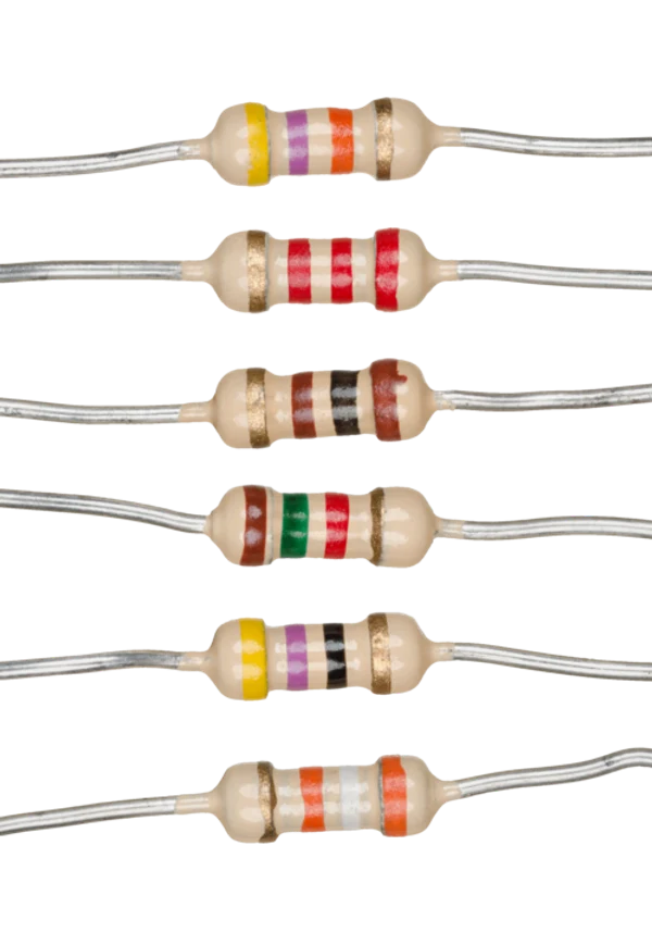
Two-resistor voltage divider for Mega TX1 to Bluetooth RX
A passive component sets current, voltage, timing, filtering, or signal behaviour without adding gain.
What it does hereIts exact value and tolerance determine how the surrounding stage behaves.
Buy / compare this part ↗Advantages
- Simple and dependable
- Low cost
- Easy to measure before installation
Limitations
- A wrong value can stop or damage the circuit
- Ratings must not be exceeded
- Polarized parts require correct orientation
Handling
- Measure unclear values
- Observe capacitor polarity
- Avoid overheating leads while soldering
Specifications to verify
- Use the exact model, value, package, and rating listed for Two-resistor voltage divider for Mega TX1 to Bluetooth RX; similar-looking parts are not always interchangeable.
- Confirm value, tolerance, power or voltage rating, polarity, and package size.
What's this?Image, role, pros, cons, handling & specifications
Common-ground wiring, terminal blocks and insulated connectors
A named project component whose exact role is defined by the source circuit and build guide.
What it does hereIt performs a documented electrical, control, interface, or construction function in this project.
Buy / compare this part ↗Advantages
- Selected for this project
- Can be checked independently
- Supports modular troubleshooting
Limitations
- Substitutes may differ
- Generic names can hide variants
- Pinouts and ratings vary
Handling
- Compare the received part with the source
- Keep it labelled
- Do not force connectors or adjusters
Specifications to verify
- Use the exact model, value, package, and rating listed for Common-ground wiring, terminal blocks and insulated connectors; similar-looking parts are not always interchangeable.
- Confirm dimensions, ratings, connection method, polarity, and environmental limits.
What's this?Image, role, pros, cons, handling & specifications
Optional camera or phone-camera module with independent power
A named project component whose exact role is defined by the source circuit and build guide.
What it does hereIt performs a documented electrical, control, interface, or construction function in this project.
Buy / compare this part ↗Advantages
- Selected for this project
- Can be checked independently
- Supports modular troubleshooting
Limitations
- Substitutes may differ
- Generic names can hide variants
- Pinouts and ratings vary
Handling
- Compare the received part with the source
- Keep it labelled
- Do not force connectors or adjusters
Specifications to verify
- Use the exact model, value, package, and rating listed for Optional camera or phone-camera module with independent power; similar-looking parts are not always interchangeable.
- Confirm dimensions, ratings, connection method, polarity, and environmental limits.
Connect one verified path at a time.
Explore the named components and standardized signal flow, then use Source Check to verify exact physical pins, values, and topology before applying power.
Trace this circuit.
Robot Snake based on Arduino controlled by Android: interactive parts, standardized terminals, responsive anchored wires, student explanations, and the original circuit reference in one shared system.
Trace before wiring
Follow power, ground, inputs, processing, and outputs in that order. Never guess a pin from package shape alone.
Connect with power off
Make short, labelled connections and share a common ground only where the schematic requires it.
Inspect every joint
Check continuity, polarity, adjacent shorts, and loose connections before the first power-up.
Open all source diagrams and build views 1 visuals
Prepare, upload, and verify the program.
Follow the same software sequence every time: verify connections, prepare the toolchain, compile, and upload.
How to connect
- Match every controller label to the circuit view and source pin map.
- Join grounds before signal wires when separate low-voltage supplies are used.
- Keep motors, relays, pumps, and other loads on a suitable driver and external supply.
Common mistakes
Reversed VCC/GND, board-label versus GPIO-number confusion, missing common ground, and charge-only USB cables.
Troubleshoot
Disconnect loads, continuity-test one path at a time, then test with a current limit.
Software preparation
- Install the current Arduino IDE or the software named in the guide.
- Install the correct board package and required libraries.
- Select the exact board, processor, and serial port.
- Compile once before connecting external loads.
How to upload code
- Connect the board with a data-capable USB cable.
- Open the documented sketch and confirm configuration values.
- Compile, fix the first reported error, and upload.
- Test with external loads disconnected first.
Common mistakes
Wrong port, missing library, incorrect board selection, boot pins held in the wrong state, or a busy serial port.
Download source code ↓Software Specifications
Arduino Compiler Programming Language: C
Circuit Atlas Reference Arduino Mega Sketch
/*
  Circuit Atlas reference sketch
  Project 302 - Android-controlled Arduino robot snake

  Target board: Arduino Mega 2560
  Required library: Servo by Arduino

  Bluetooth commands (send as single characters from a serial-terminal app):
    F = forward wave       B = reverse wave
    L = curve left         R = curve right
    S = stop and centre    A = autonomous IR avoidance
    1..5 = gait speed      ? = print command help

  POWER SAFETY
  - Twelve servos require a separate, high-current regulated 5-6 V supply.
  - Do not connect a raw 7.4 V battery directly to standard 5-6 V servos.
  - Never power the servos from the Mega 5 V pin.
  - Join the servo-supply, Bluetooth, sensor, and Mega grounds together.
  - Add bulk capacitance near the servo power bus and fuse the battery lead.
*/

#include <Servo.h>
#include <math.h>

constexpr uint8_t SEGMENT_COUNT = 12;
constexpr uint8_t SERVO_PINS[SEGMENT_COUNT] = {
  2, 3, 4, 5, 6, 7, 8, 9, 10, 11, 12, 13
};

// Optional digital obstacle sensor. Most IR modules pull LOW near an object.
constexpr uint8_t IR_OBSTACLE_PIN = 22;
constexpr bool IR_ACTIVE_LOW = true;

constexpr int SERVO_CENTRE_DEG = 90;
constexpr int SERVO_MIN_DEG = 35;
constexpr int SERVO_MAX_DEG = 145;
constexpr float BASE_AMPLITUDE_DEG = 34.0F;
constexpr float SEGMENT_PHASE_RAD = 0.62F;
constexpr unsigned long FRAME_INTERVAL_MS = 20;
constexpr unsigned long OBSTACLE_TURN_MS = 1250;

Servo segments[SEGMENT_COUNT];

enum class Gait : uint8_t {
  Stopped,
  Forward,
  Reverse,
  Left,
  Right,
  Autonomous
};

Gait gait = Gait::Stopped;
float wavePhase = 0.0F;
float phaseStep = 0.13F;
unsigned long lastFrameMs = 0;
unsigned long avoidanceUntilMs = 0;
bool avoidanceTurnLeft = true;

bool obstacleDetected() {
  const bool level = digitalRead(IR_OBSTACLE_PIN);
  return IR_ACTIVE_LOW ? level == LOW : level == HIGH;
}

void centreSnake() {
  for (uint8_t index = 0; index < SEGMENT_COUNT; ++index) {
    segments[index].write(SERVO_CENTRE_DEG);
  }
}

void printHelp() {
  Serial.println(F("Commands: F forward, B reverse, L left, R right"));
  Serial.println(F("          S stop, A autonomous, 1..5 speed, ? help"));
  Serial1.println(F("F/B/L/R/S/A, speed 1..5, ? help"));
}

void setSpeedFromCommand(char command) {
  const uint8_t level = static_cast<uint8_t>(command - '0');
  phaseStep = 0.07F + (0.025F * level);
  Serial.print(F("Gait speed level: "));
  Serial.println(level);
}

void handleCommand(char command) {
  if (command >= 'a' && command <= 'z') command -= 32;

  switch (command) {
    case 'F': gait = Gait::Forward; break;
    case 'B': gait = Gait::Reverse; break;
    case 'L': gait = Gait::Left; break;
    case 'R': gait = Gait::Right; break;
    case 'A': gait = Gait::Autonomous; break;
    case 'S':
      gait = Gait::Stopped;
      centreSnake();
      break;
    case '1': case '2': case '3': case '4': case '5':
      setSpeedFromCommand(command);
      break;
    case '?': printHelp(); break;
    case '\r': case '\n': case ' ': break;
    default:
      Serial.print(F("Ignored command: "));
      Serial.println(command);
      return;
  }

  Serial.print(F("Accepted command: "));
  Serial.println(command);
}

void readCommands() {
  while (Serial1.available() > 0) handleCommand(static_cast<char>(Serial1.read()));
  while (Serial.available() > 0) handleCommand(static_cast<char>(Serial.read()));
}

void updateAutonomousState() {
  if (gait != Gait::Autonomous) return;

  const unsigned long now = millis();
  if (obstacleDetected() && now >= avoidanceUntilMs) {
    avoidanceUntilMs = now + OBSTACLE_TURN_MS;
    avoidanceTurnLeft = !avoidanceTurnLeft;
  }
}

void writeWaveFrame() {
  const unsigned long now = millis();
  if (now - lastFrameMs < FRAME_INTERVAL_MS) return;
  lastFrameMs = now;

  if (gait == Gait::Stopped) return;

  updateAutonomousState();

  float direction = 1.0F;
  float turnBiasDeg = 0.0F;
  float amplitudeDeg = BASE_AMPLITUDE_DEG;

  switch (gait) {
    case Gait::Reverse:
      direction = -1.0F;
      break;
    case Gait::Left:
      turnBiasDeg = -13.0F;
      amplitudeDeg = 27.0F;
      break;
    case Gait::Right:
      turnBiasDeg = 13.0F;
      amplitudeDeg = 27.0F;
      break;
    case Gait::Autonomous:
      if (now < avoidanceUntilMs) {
        turnBiasDeg = avoidanceTurnLeft ? -18.0F : 18.0F;
        amplitudeDeg = 25.0F;
      }
      break;
    case Gait::Forward:
    case Gait::Stopped:
      break;
  }

  for (uint8_t index = 0; index < SEGMENT_COUNT; ++index) {
    // Alternating a small bias keeps a turn smooth across the body instead of
    // forcing every joint against the same mechanical limit.
    const float jointPhase = wavePhase + (direction * index * SEGMENT_PHASE_RAD);
    const float distributedBias = turnBiasDeg * (0.35F + 0.65F * index / (SEGMENT_COUNT - 1.0F));
    const int angle = constrain(
      static_cast<int>(SERVO_CENTRE_DEG + amplitudeDeg * sin(jointPhase) + distributedBias),
      SERVO_MIN_DEG,
      SERVO_MAX_DEG
    );
    segments[index].write(angle);
  }

  wavePhase += direction * phaseStep;
  if (wavePhase > TWO_PI) wavePhase -= TWO_PI;
  if (wavePhase < 0.0F) wavePhase += TWO_PI;
}

void setup() {
  pinMode(IR_OBSTACLE_PIN, INPUT_PULLUP);

  Serial.begin(115200);
  // HC-05/HC-06: Mega RX1=19 receives module TX; Mega TX1=18 sends through
  // a voltage divider to module RX when the breakout is not 5 V tolerant.
  Serial1.begin(9600);

  for (uint8_t index = 0; index < SEGMENT_COUNT; ++index) {
    segments[index].attach(SERVO_PINS[index]);
  }
  centreSnake();

  Serial.println(F("Circuit Atlas robot snake ready"));
  printHelp();
  delay(700);
}

void loop() {
  readCommands();
  writeWaveFrame();
}
Assemble, deploy, test, and troubleshoot.
Use the complete source notes in build order, then pass the final checks before calling the project finished.
Build in functional stages
- Power and regulation
- Controller or processing stage
- Inputs and sensors
- Outputs and loads
- Enclosure and strain relief
Power up safely
- Inspect unpowered continuity first
- Apply the lowest safe current limit
- Measure supply rails before signals
- Add one load at a time
- Record expected and actual results
Work from simple to complex
- Confirm power, ground, polarity, and orientation
- Compare each pin with the source
- Test inputs separately from outputs
- Replace only one variable at a time
- Power off before every correction
Follow the documented instructions.
These notes come from this project's source and remain in their original order.
Project overview
Project build noteTwelve servo motors drive the snake's segments, which are joined with metal brackets. A 7.4-volt battery pack powers the servos and controls them with
an Arduino Mega. An android app can be used to control the snake using Bluetooth.
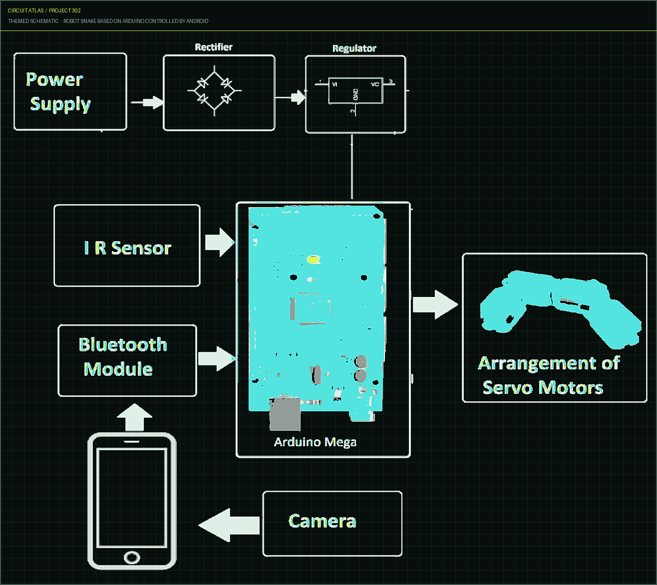
Block Diagram
Project build noteIn addition to autonomous movement, the snake is additionally capable of passive activity. Various different types of servos and brackets can be used to construct such a robot. There are 12 segments of the robot, each containing a servo motor, a C-bracket, a side bracket, a set of Lego wheels, and a wire clip. The Lego wheel axle must have two screw holes for the C-bracket to be attached to it. In spite of the fact that nine segments are already connected, they need to be expanded with two tail segments in order to accommodate
the Arduino and batteries. The side brackets and C-brackets are connected to the side brackets. A 5AA battery holder is used to power the Arduino and therefore the tail of the snake. A separate energy supply powers the servos. That is the 7.4-volt battery pack. The voltage pin is attached to a five-volt Arduino pin. On the receiver, the lower pin is attached to ground.
Hardware Specifications
Project build noteArduino mega IR Sensor Servo Motors Bluetooth module Camera Cables and Connectors PCB and Breadboards Push Buttons Switch IC
Reference Wiring and Power Distribution
Project build noteThis Circuit Atlas implementation uses an Arduino Mega because twelve independent servo channels are required. Connect servo signals for body segments 1-12 to Mega pins D2-D13. Connect the digital IR obstacle output to D22. Connect Bluetooth TX to Mega RX1 pin 19 and Bluetooth RX to Mega TX1 pin 18 through a voltage divider if the module input is not 5 V tolerant.
Power all twelve servos from a separate regulated 5-6 V high-current rail. A raw 7.4 V two-cell battery can damage standard servos, so place a correctly rated UBEC or buck regulator between that battery and the servo bus. Fit a fuse, add at least 4700 uF near the servo distribution point, and connect the servo, Bluetooth, sensor and Mega grounds together. Do not route servo current through the Mega 5 V pin.
Android Bluetooth Command Protocol
Project build notePair the phone with the HC-05 or HC-06 and use any Bluetooth serial-terminal app at 9600 baud. Configure buttons to transmit single characters: F for forward, B for reverse, L or R for curved movement, S to stop and centre all joints, and A for autonomous IR-obstacle avoidance. Characters 1 through 5 select gait speed. The same commands can be tested through the USB Serial Monitor at 115200 baud before Bluetooth is connected.
Servo Alignment and First Test
Project build note1. Disconnect the body links, remove the servo horns and upload the sketch with the snake raised off the bench. 2. Send S so every servo moves to 90 degrees, then refit each horn with its segment mechanically centred. 3. Reconnect the brackets and test speed 1 before trying faster gaits. Reduce BASE_AMPLITUDE_DEG if any joint binds or reaches its stop. 4. Verify the IR module changes state near an obstacle; change IR_ACTIVE_LOW if its logic is reversed. 5. Test Bluetooth commands while the servo supply is current-limited and watch for regulator heating or voltage sag. 6. Secure batteries and cables so the body cannot pinch them. This educational robot is not a rescue, surveillance or life-safety device.
You built Robot Snake based on Arduino controlled by Android.
You followed the full workflow from understanding the mission to testing the finished project. That is a real engineering achievement - well done.
Intelligent Gas Leakage Detector based on IoT
Ready to reuse what you learned in another project from the same track?
Start this project →