Interfacing Hall Effect Sensor with Arduino
The use of sensors has always been crucial to any project. It is these that create the digital/variable data that is used by electronics to process the real- time environmental data. The…
Know the mission before touching a wire.
Understand what you are making, prepare the right tools, and make the workbench safe.
Project details
Interfacing Hall Effect Sensor with Arduino is a arduino project. The use of sensors has always been crucial to any project. It is these that create the digital/variable data that is used by electronics to process the real- time environmental data. The…
- Source pages
- 861-864
- Named parts
- 3
- Build goal
- Working, tested prototype
Tools you need
- Digital multimeter
- Wire stripper and side cutters
- Soldering iron with a fine tip
- Current-limited bench supply
- Computer with a data-capable USB cable
Use eye protection, good lighting, and a clean insulated surface throughout the build.
Safety precautions
- Disconnect every power source before changing a connection.
- Check component polarity, pinout, and supply voltage twice.
- Use a current limit for the first power-up.
- Keep liquids, loose metal, and uninsulated wires away from the bench.
Gather, identify, and understand every part.
Use the standardized inventory, then open What's this? to learn each part's role, advantages, limitations, handling, and specifications.
What's this?Image, role, pros, cons, handling & specifications
Hall Effect Sensor (any digital version)
A sensor converts a physical condition into an electrical signal the circuit can measure.
What it does hereIt provides project input as an analogue, digital, resistive, frequency, or calibrated signal.
Buy / compare this part ↗Advantages
- Adds real-world awareness
- Can usually be tested independently
- Often supports calibration
Limitations
- Readings can drift
- Placement affects results
- Some sensors need warm-up or calibration
Handling
- Protect the sensing surface
- Observe supply voltage and polarity
- Keep signal leads away from noisy power wiring
Specifications to verify
- Use the exact model, value, package, and rating listed for Hall Effect Sensor (any digital version); similar-looking parts are not always interchangeable.
- Confirm supply range, output type, measurement range, accuracy, response time, and pin order.
What's this?Image, role, pros, cons, handling & specifications
Arduino (Any version)
A programmable controller that reads inputs, makes decisions, and drives the project's outputs.
What it does hereIt is the control centre and must use the documented board, pin map, supply, and logic level.
Buy / compare this part ↗Advantages
- Reprogrammable and reusable
- Large learning ecosystem
- Complex behaviour remains changeable
Limitations
- GPIO voltage and current are limited
- Some pins affect boot or communication
- Loads normally need a driver
Handling
- Disconnect power before rewiring
- Avoid static discharge
- Never power motors, relays, or pumps directly from GPIO
Specifications to verify
- Use the exact model, value, package, and rating listed for Arduino (Any version); similar-looking parts are not always interchangeable.
- Confirm operating voltage, logic level, pinout, memory, USB interface, and maximum GPIO current.
What's this?Image, role, pros, cons, handling & specifications
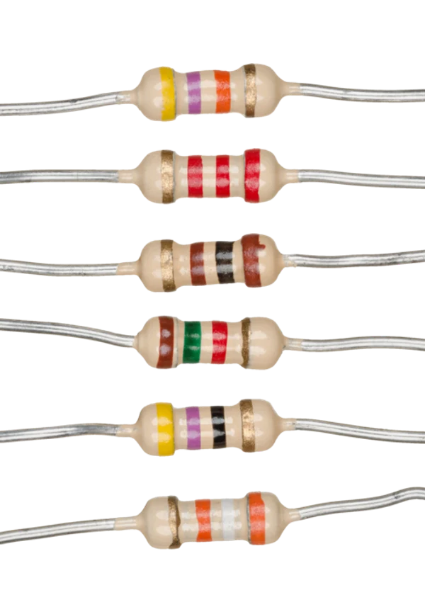 PASSIVE LEARNING VIEW
k ohm and 1K ohm Resistor
A passive component sets current, voltage, timing, filtering, or signal behaviour without adding gain.
What it does hereIts exact value and tolerance determine how the surrounding stage behaves.
Buy / compare this part ↗Advantages
- Simple and dependable
- Low cost
- Easy to measure before installation
Limitations
- A wrong value can stop or damage the circuit
- Ratings must not be exceeded
- Polarized parts require correct orientation
Handling
- Measure unclear values
- Observe capacitor polarity
- Avoid overheating leads while soldering
Specifications to verify
- Use the exact model, value, package, and rating listed for k ohm and 1K ohm Resistor; similar-looking parts are not always interchangeable.
- Confirm value, tolerance, power or voltage rating, polarity, and package size.
Connect one verified path at a time.
Explore the named components and standardized signal flow, then use Source Check to verify exact physical pins, values, and topology before applying power.
Trace this circuit.
Interfacing Hall Effect Sensor with Arduino: interactive parts, standardized terminals, responsive anchored wires, student explanations, and the original circuit reference in one shared system.
Trace before wiring
Follow power, ground, inputs, processing, and outputs in that order. Never guess a pin from package shape alone.
Connect with power off
Make short, labelled connections and share a common ground only where the schematic requires it.
Inspect every joint
Check continuity, polarity, adjacent shorts, and loose connections before the first power-up.
Open all source diagrams and build views 1 visuals
Confirm the hardware-only control path.
This project does not include firmware in the source. The circuit itself provides the required behaviour.
How to connect
- Match every controller label to the circuit view and source pin map.
- Join grounds before signal wires when separate low-voltage supplies are used.
- Keep motors, relays, pumps, and other loads on a suitable driver and external supply.
Common mistakes
Reversed VCC/GND, board-label versus GPIO-number confusion, missing common ground, and charge-only USB cables.
Troubleshoot
Disconnect loads, continuity-test one path at a time, then test with a current limit.
Software preparation
No IDE, board package, library, or firmware upload is required for this project.
If you add a programmable controller as an extension, document its pin map separately.
How to upload code
The original design is implemented entirely in hardware, so proceed after verifying the circuit and supply.
Assemble, deploy, test, and troubleshoot.
Use the complete source notes in build order, then pass the final checks before calling the project finished.
Build in functional stages
- Power and regulation
- Controller or processing stage
- Inputs and sensors
- Outputs and loads
- Enclosure and strain relief
Power up safely
- Inspect unpowered continuity first
- Apply the lowest safe current limit
- Measure supply rails before signals
- Add one load at a time
- Record expected and actual results
Work from simple to complex
- Confirm power, ground, polarity, and orientation
- Compare each pin with the source
- Test inputs separately from outputs
- Replace only one variable at a time
- Power off before every correction
Follow the documented instructions.
These notes come from this project's source and remain in their original order.
Project overview
Project build noteThe use of sensors has always been crucial to any project. It is these that create the digital/variable data that is used by electronics to process the real- time environmental data. The market offers many types of sensors, and you can choose one that suits your needs. We will use an Arduino to create a project that uses Hall sensors, also known as Hall effect sensors. Using the magnet sensor, you can determine the magnet's pole as well as detect its magnetic field. Magnets are detected for what reason? Perhaps you'd like to know. Actually, there are a number of applications that use Hall Effect sensors, but most of us probably are unaware of them. The speed of rotating machines or bicycles can be measured using this sensor. BLDC motors also utilize this sensor to track the Rotor Magnet position and immediately activate the Stator coils accordingly. Let's learn how to add another tool to our arsenal by learning how to interface Hall effect sensors with Arduino. Some projects involving
Hall sensors are as follows
Project build noteAs part of this tutorial, we will utilize Arduino interrupts to detect a magnet near a Hall sensor and flash an LED. We will use interrupts in our tutorial as well, since Hall sensors will typically only be used with interrupts due to their applications that require high reading and executing speeds.
Materials Required
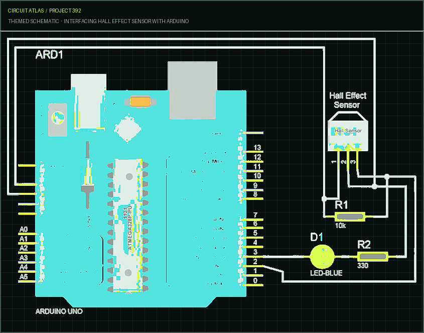
Project build noteHall Effect Sensor (any digital version) Arduino (Any version) 10k ohm and 1K ohm Resistor LED Connecting Wires
Hall Effect Sensors
Project build noteSeveral things should be kept in mind before we dive into the connections for Hall Effect sensors. Digital Hall sensors and analog Hall sensors are the two main types of Hall sensors. As opposed to the digital Hall sensor, which detects whether a magnet is present or not (0 or 1). The analog Hall sensor, on the other hand, can detect the strength of or the distance from the magnet, based on its output. Because these are the most common digital Hall sensors, this project will only focus on them. By its name, Hall Effect sensors work on the basis of the "Hall Effect". Having carried out this experiment the law states that when current flows perpendicular to the direction that the current is flowing, a voltage can be measured at the angle at which the current flows. It will be possible for the hall sensor to detect magnets around it using this technique. I'm done with theory, let's move onto hardware.
Circuit Diagram and Explanation
Project build noteThis circuit diagram demonstrates how to connect a Hall sensor to an Arduino. This Arduino circuit diagram for a Hall Effect sensor is quite straightforward as you can see. It is when we try to figure out hall sensor pin numbers that we usually make mistakes. When positioned face-on, the Vcc and Ground pins are on the left, followed by the Signal pin. As we mentioned earlier, we will use interrupts, which is why pin 2 of the Arduino is connected to the output pin of the Hall sensor. Magnets are detected by switching on the Pin, which is connected to an LED.
Arduino Hall Effect Sensor Working
Project build noteYou can now upload the Arduino code once you have created your code and hardware. A 9V battery has been used to power the entire setup. Power can be provided by any preferred source. You will see the LED light up as soon
as you place the magnet close to the sensor and it will turn off as soon as you remove the magnet. Note: Hall sensors are pole sensitive, which means that each side of the sensor can either detect only the North Pole or only the South Pole, only one side of the sensor can detect both poles. Thus, if you bring the north sensing surface close to the south pole, the LED will not glow. Throughout the sensor, we bring the magnet near to it, causing it to change its state when we do that. An interrupt pin is triggered by this change, which then calls the toggle function, which changes the variable "state" from 0 to 1. In this way, the LED will illuminate. Once the magnet is moved away from the sensor, the sensor output will again change. We notice that this changes again by using an interrupt statement and thus the variable "state" is set to zero. The LED will darken if the switch is turned off. Each time you approach the sensor with a magnet, the same happens.
You built Interfacing Hall Effect Sensor with Arduino.
You followed the full workflow from understanding the mission to testing the finished project. That is a real engineering achievement - well done.
Automatic Call answering Machine using Arduino and GSM Module
Ready to reuse what you learned in another project from the same track?
Start this project →