ESP8266 NodeMCU Plot Sensor Readings in Charts (Multiple Series)
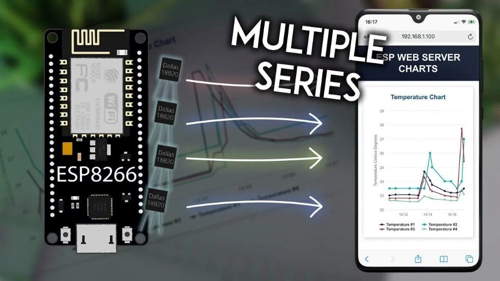
Series) This project demonstrates how to construct a web server using the ESP8266 NodeMCU board so that sensor readings can be plotted in charts that contain more than one series. On the…
Know the mission before touching a wire.
Understand what you are making, prepare the right tools, and make the workbench safe.
Project details
ESP8266 NodeMCU Plot Sensor Readings in Charts (Multiple Series) is a iot project. Series) This project demonstrates how to construct a web server using the ESP8266 NodeMCU board so that sensor readings can be plotted in charts that contain more than one series. On the…
- Source pages
- 996-1005
- Named parts
- 18
- Build goal
- Working, tested prototype
Tools you need
- Digital multimeter
- Wire stripper and side cutters
- Soldering iron with a fine tip
- Current-limited bench supply
- Computer with a data-capable USB cable
Use eye protection, good lighting, and a clean insulated surface throughout the build.
Safety precautions
- Disconnect every power source before changing a connection.
- Check component polarity, pinout, and supply voltage twice.
- Use a current limit for the first power-up.
- Keep liquids, loose metal, and uninsulated wires away from the bench.
Gather, identify, and understand every part.
Use the standardized inventory, then open What's this? to learn each part's role, advantages, limitations, handling, and specifications.
What's this?Image, role, pros, cons, handling & specifications
ESP8266 (read Best ESP8266 development boards)
A programmable controller that reads inputs, makes decisions, and drives the project's outputs.
What it does hereIt is the control centre and must use the documented board, pin map, supply, and logic level.
Buy / compare this part ↗Advantages
- Reprogrammable and reusable
- Large learning ecosystem
- Complex behaviour remains changeable
Limitations
- GPIO voltage and current are limited
- Some pins affect boot or communication
- Loads normally need a driver
Handling
- Disconnect power before rewiring
- Avoid static discharge
- Never power motors, relays, or pumps directly from GPIO
Specifications to verify
- Use the exact model, value, package, and rating listed for ESP8266 (read Best ESP8266 development boards); similar-looking parts are not always interchangeable.
- Confirm operating voltage, logic level, pinout, memory, USB interface, and maximum GPIO current.
What's this?Image, role, pros, cons, handling & specifications
x DS18B20 temperature sensor (one or multiple sensors), in a
A sensor converts a physical condition into an electrical signal the circuit can measure.
What it does hereIt provides project input as an analogue, digital, resistive, frequency, or calibrated signal.
Buy / compare this part ↗Advantages
- Adds real-world awareness
- Can usually be tested independently
- Often supports calibration
Limitations
- Readings can drift
- Placement affects results
- Some sensors need warm-up or calibration
Handling
- Protect the sensing surface
- Observe supply voltage and polarity
- Keep signal leads away from noisy power wiring
Specifications to verify
- Use the exact model, value, package, and rating listed for x DS18B20 temperature sensor (one or multiple sensors), in a; similar-looking parts are not always interchangeable.
- Confirm supply range, output type, measurement range, accuracy, response time, and pin order.
What's this?Image, role, pros, cons, handling & specifications
water-resistant version
A named project component whose exact role is defined by the source circuit and build guide.
What it does hereIt performs a documented electrical, control, interface, or construction function in this project.
Buy / compare this part ↗Advantages
- Selected for this project
- Can be checked independently
- Supports modular troubleshooting
Limitations
- Substitutes may differ
- Generic names can hide variants
- Pinouts and ratings vary
Handling
- Compare the received part with the source
- Keep it labelled
- Do not force connectors or adjusters
Specifications to verify
- Use the exact model, value, package, and rating listed for water-resistant version; similar-looking parts are not always interchangeable.
- Confirm dimensions, ratings, connection method, polarity, and environmental limits.
What's this?Image, role, pros, cons, handling & specifications
 PASSIVE LEARNING VIEW
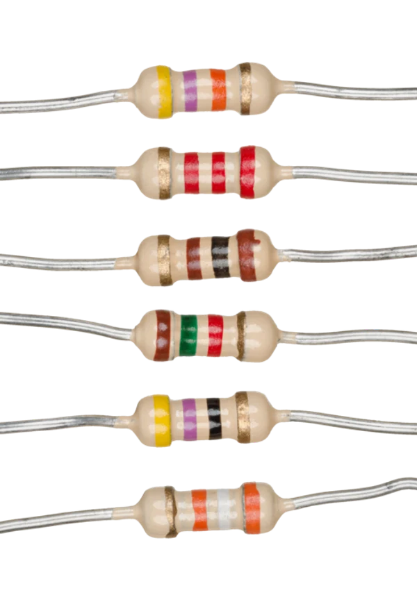
k Ohm resistor
A passive component sets current, voltage, timing, filtering, or signal behaviour without adding gain.
What it does hereIts exact value and tolerance determine how the surrounding stage behaves.
Buy / compare this part ↗Advantages
- Simple and dependable
- Low cost
- Easy to measure before installation
Limitations
- A wrong value can stop or damage the circuit
- Ratings must not be exceeded
- Polarized parts require correct orientation
Handling
- Measure unclear values
- Observe capacitor polarity
- Avoid overheating leads while soldering
Specifications to verify
- Use the exact model, value, package, and rating listed for k Ohm resistor; similar-looking parts are not always interchangeable.
- Confirm value, tolerance, power or voltage rating, polarity, and package size.
What's this?Image, role, pros, cons, handling & specifications
A set of jumper wires
A named project component whose exact role is defined by the source circuit and build guide.
What it does hereIt performs a documented electrical, control, interface, or construction function in this project.
Buy / compare this part ↗Advantages
- Selected for this project
- Can be checked independently
- Supports modular troubleshooting
Limitations
- Substitutes may differ
- Generic names can hide variants
- Pinouts and ratings vary
Handling
- Compare the received part with the source
- Keep it labelled
- Do not force connectors or adjusters
Specifications to verify
- Use the exact model, value, package, and rating listed for A set of jumper wires; similar-looking parts are not always interchangeable.
- Confirm dimensions, ratings, connection method, polarity, and environmental limits.
What's this?Image, role, pros, cons, handling & specifications
Prerequisites
A named project component whose exact role is defined by the source circuit and build guide.
What it does hereIt performs a documented electrical, control, interface, or construction function in this project.
Buy / compare this part ↗Advantages
- Selected for this project
- Can be checked independently
- Supports modular troubleshooting
Limitations
- Substitutes may differ
- Generic names can hide variants
- Pinouts and ratings vary
Handling
- Compare the received part with the source
- Keep it labelled
- Do not force connectors or adjusters
Specifications to verify
- Use the exact model, value, package, and rating listed for Prerequisites; similar-looking parts are not always interchangeable.
- Confirm dimensions, ratings, connection method, polarity, and environmental limits.
What's this?Image, role, pros, cons, handling & specifications
Open the Arduino Software and Install the ESP8266 Board
A programmable controller that reads inputs, makes decisions, and drives the project's outputs.
What it does hereIt is the control centre and must use the documented board, pin map, supply, and logic level.
Buy / compare this part ↗Advantages
- Reprogrammable and reusable
- Large learning ecosystem
- Complex behaviour remains changeable
Limitations
- GPIO voltage and current are limited
- Some pins affect boot or communication
- Loads normally need a driver
Handling
- Disconnect power before rewiring
- Avoid static discharge
- Never power motors, relays, or pumps directly from GPIO
Specifications to verify
- Use the exact model, value, package, and rating listed for Open the Arduino Software and Install the ESP8266 Board; similar-looking parts are not always interchangeable.
- Confirm operating voltage, logic level, pinout, memory, USB interface, and maximum GPIO current.
What's this?Image, role, pros, cons, handling & specifications
Filesystem Uploader Plugin
A named project component whose exact role is defined by the source circuit and build guide.
What it does hereIt performs a documented electrical, control, interface, or construction function in this project.
Buy / compare this part ↗Advantages
- Selected for this project
- Can be checked independently
- Supports modular troubleshooting
Limitations
- Substitutes may differ
- Generic names can hide variants
- Pinouts and ratings vary
Handling
- Compare the received part with the source
- Keep it labelled
- Do not force connectors or adjusters
Specifications to verify
- Use the exact model, value, package, and rating listed for Filesystem Uploader Plugin; similar-looking parts are not always interchangeable.
- Confirm dimensions, ratings, connection method, polarity, and environmental limits.
What's this?Image, role, pros, cons, handling & specifications
Installing Libraries
A named project component whose exact role is defined by the source circuit and build guide.
What it does hereIt performs a documented electrical, control, interface, or construction function in this project.
Buy / compare this part ↗Advantages
- Selected for this project
- Can be checked independently
- Supports modular troubleshooting
Limitations
- Substitutes may differ
- Generic names can hide variants
- Pinouts and ratings vary
Handling
- Compare the received part with the source
- Keep it labelled
- Do not force connectors or adjusters
Specifications to verify
- Use the exact model, value, package, and rating listed for Installing Libraries; similar-looking parts are not always interchangeable.
- Confirm dimensions, ratings, connection method, polarity, and environmental limits.
What's this?Image, role, pros, cons, handling & specifications
by the Arduino Library Manager; DallasTemperature, which is also managed
A programmable controller that reads inputs, makes decisions, and drives the project's outputs.
What it does hereIt is the control centre and must use the documented board, pin map, supply, and logic level.
Buy / compare this part ↗Advantages
- Reprogrammable and reusable
- Large learning ecosystem
- Complex behaviour remains changeable
Limitations
- GPIO voltage and current are limited
- Some pins affect boot or communication
- Loads normally need a driver
Handling
- Disconnect power before rewiring
- Avoid static discharge
- Never power motors, relays, or pumps directly from GPIO
Specifications to verify
- Use the exact model, value, package, and rating listed for by the Arduino Library Manager; DallasTemperature, which is also managed; similar-looking parts are not always interchangeable.
- Confirm operating voltage, logic level, pinout, memory, USB interface, and maximum GPIO current.
What's this?Image, role, pros, cons, handling & specifications
Manager)
A named project component whose exact role is defined by the source circuit and build guide.
What it does hereIt performs a documented electrical, control, interface, or construction function in this project.
Buy / compare this part ↗Advantages
- Selected for this project
- Can be checked independently
- Supports modular troubleshooting
Limitations
- Substitutes may differ
- Generic names can hide variants
- Pinouts and ratings vary
Handling
- Compare the received part with the source
- Keep it labelled
- Do not force connectors or adjusters
Specifications to verify
- Use the exact model, value, package, and rating listed for Manager); similar-looking parts are not always interchangeable.
- Confirm dimensions, ratings, connection method, polarity, and environmental limits.
What's this?Image, role, pros, cons, handling & specifications
Library Installation (VS Code + PlatformIO)
A named project component whose exact role is defined by the source circuit and build guide.
What it does hereIt performs a documented electrical, control, interface, or construction function in this project.
Buy / compare this part ↗Advantages
- Selected for this project
- Can be checked independently
- Supports modular troubleshooting
Limitations
- Substitutes may differ
- Generic names can hide variants
- Pinouts and ratings vary
Handling
- Compare the received part with the source
- Keep it labelled
- Do not force connectors or adjusters
Specifications to verify
- Use the exact model, value, package, and rating listed for Library Installation (VS Code + PlatformIO); similar-looking parts are not always interchangeable.
- Confirm dimensions, ratings, connection method, polarity, and environmental limits.
What's this?Image, role, pros, cons, handling & specifications
(for instance, sensor readings received via MQTT, ESP-NOW, or random
A sensor converts a physical condition into an electrical signal the circuit can measure.
What it does hereIt provides project input as an analogue, digital, resistive, frequency, or calibrated signal.
Buy / compare this part ↗Advantages
- Adds real-world awareness
- Can usually be tested independently
- Often supports calibration
Limitations
- Readings can drift
- Placement affects results
- Some sensors need warm-up or calibration
Handling
- Protect the sensing surface
- Observe supply voltage and polarity
- Keep signal leads away from noisy power wiring
Specifications to verify
- Use the exact model, value, package, and rating listed for (for instance, sensor readings received via MQTT, ESP-NOW, or random; similar-looking parts are not always interchangeable.
- Confirm supply range, output type, measurement range, accuracy, response time, and pin order.
What's this?Image, role, pros, cons, handling & specifications
values—to experiment with this project...)
A named project component whose exact role is defined by the source circuit and build guide.
What it does hereIt performs a documented electrical, control, interface, or construction function in this project.
Buy / compare this part ↗Advantages
- Selected for this project
- Can be checked independently
- Supports modular troubleshooting
Limitations
- Substitutes may differ
- Generic names can hide variants
- Pinouts and ratings vary
Handling
- Compare the received part with the source
- Keep it labelled
- Do not force connectors or adjusters
Specifications to verify
- Use the exact model, value, package, and rating listed for values—to experiment with this project...); similar-looking parts are not always interchangeable.
- Confirm dimensions, ratings, connection method, polarity, and environmental limits.
What's this?Image, role, pros, cons, handling & specifications
Sensor 1: 28 FF A0 11 33 17 3 96
A sensor converts a physical condition into an electrical signal the circuit can measure.
What it does hereIt provides project input as an analogue, digital, resistive, frequency, or calibrated signal.
Buy / compare this part ↗Advantages
- Adds real-world awareness
- Can usually be tested independently
- Often supports calibration
Limitations
- Readings can drift
- Placement affects results
- Some sensors need warm-up or calibration
Handling
- Protect the sensing surface
- Observe supply voltage and polarity
- Keep signal leads away from noisy power wiring
Specifications to verify
- Use the exact model, value, package, and rating listed for Sensor 1: 28 FF A0 11 33 17 3 96; similar-looking parts are not always interchangeable.
- Confirm supply range, output type, measurement range, accuracy, response time, and pin order.
What's this?Image, role, pros, cons, handling & specifications
Sensor 2: 28 FF B4 6 33 17 3 4B
A sensor converts a physical condition into an electrical signal the circuit can measure.
What it does hereIt provides project input as an analogue, digital, resistive, frequency, or calibrated signal.
Buy / compare this part ↗Advantages
- Adds real-world awareness
- Can usually be tested independently
- Often supports calibration
Limitations
- Readings can drift
- Placement affects results
- Some sensors need warm-up or calibration
Handling
- Protect the sensing surface
- Observe supply voltage and polarity
- Keep signal leads away from noisy power wiring
Specifications to verify
- Use the exact model, value, package, and rating listed for Sensor 2: 28 FF B4 6 33 17 3 4B; similar-looking parts are not always interchangeable.
- Confirm supply range, output type, measurement range, accuracy, response time, and pin order.
What's this?Image, role, pros, cons, handling & specifications
Sensor 3: 28 FF 11 28 33 18 1 6B
A sensor converts a physical condition into an electrical signal the circuit can measure.
What it does hereIt provides project input as an analogue, digital, resistive, frequency, or calibrated signal.
Buy / compare this part ↗Advantages
- Adds real-world awareness
- Can usually be tested independently
- Often supports calibration
Limitations
- Readings can drift
- Placement affects results
- Some sensors need warm-up or calibration
Handling
- Protect the sensing surface
- Observe supply voltage and polarity
- Keep signal leads away from noisy power wiring
Specifications to verify
- Use the exact model, value, package, and rating listed for Sensor 3: 28 FF 11 28 33 18 1 6B; similar-looking parts are not always interchangeable.
- Confirm supply range, output type, measurement range, accuracy, response time, and pin order.
What's this?Image, role, pros, cons, handling & specifications
Sensor 4: 28 FF 43 F5 32 18 2 A8
A sensor converts a physical condition into an electrical signal the circuit can measure.
What it does hereIt provides project input as an analogue, digital, resistive, frequency, or calibrated signal.
Buy / compare this part ↗Advantages
- Adds real-world awareness
- Can usually be tested independently
- Often supports calibration
Limitations
- Readings can drift
- Placement affects results
- Some sensors need warm-up or calibration
Handling
- Protect the sensing surface
- Observe supply voltage and polarity
- Keep signal leads away from noisy power wiring
Specifications to verify
- Use the exact model, value, package, and rating listed for Sensor 4: 28 FF 43 F5 32 18 2 A8; similar-looking parts are not always interchangeable.
- Confirm supply range, output type, measurement range, accuracy, response time, and pin order.
Connect one verified path at a time.
Explore the named components and standardized signal flow, then use Source Check to verify exact physical pins, values, and topology before applying power.
Trace this circuit.
ESP8266 NodeMCU Plot Sensor Readings in Charts (Multiple Series): interactive parts, standardized terminals, responsive anchored wires, student explanations, and the original circuit reference in one shared system.
Trace before wiring
Follow power, ground, inputs, processing, and outputs in that order. Never guess a pin from package shape alone.
Connect with power off
Make short, labelled connections and share a common ground only where the schematic requires it.
Inspect every joint
Check continuity, polarity, adjacent shorts, and loose connections before the first power-up.
Open all source diagrams and build views 7 visuals
Confirm the hardware-only control path.
This project does not include firmware in the source. The circuit itself provides the required behaviour.
How to connect
- Match every controller label to the circuit view and source pin map.
- Join grounds before signal wires when separate low-voltage supplies are used.
- Keep motors, relays, pumps, and other loads on a suitable driver and external supply.
Common mistakes
Reversed VCC/GND, board-label versus GPIO-number confusion, missing common ground, and charge-only USB cables.
Troubleshoot
Disconnect loads, continuity-test one path at a time, then test with a current limit.
Software preparation
No IDE, board package, library, or firmware upload is required for this project.
If you add a programmable controller as an extension, document its pin map separately.
How to upload code
The original design is implemented entirely in hardware, so proceed after verifying the circuit and supply.
Assemble, deploy, test, and troubleshoot.
Use the complete source notes in build order, then pass the final checks before calling the project finished.
Build in functional stages
- Power and regulation
- Controller or processing stage
- Inputs and sensors
- Outputs and loads
- Enclosure and strain relief
Power up safely
- Inspect unpowered continuity first
- Apply the lowest safe current limit
- Measure supply rails before signals
- Add one load at a time
- Record expected and actual results
Work from simple to complex
- Confirm power, ground, polarity, and orientation
- Compare each pin with the source
- Test inputs separately from outputs
- Replace only one variable at a time
- Power off before every correction
Follow the documented instructions.
These notes come from this project's source and remain in their original order.
Project overview
Project build noteSeries) This project demonstrates how to construct a web server using the ESP8266 NodeMCU board so that sensor readings can be plotted in charts that contain more than one series. On the same chart, we will plot the readings from four different DS18B20 temperature sensors so that you can see how this works. You are free to modify the project in order to plot any other data you require. We will be utilizing the Highcharts JavaScript library in order to create the charts.
Project Overview
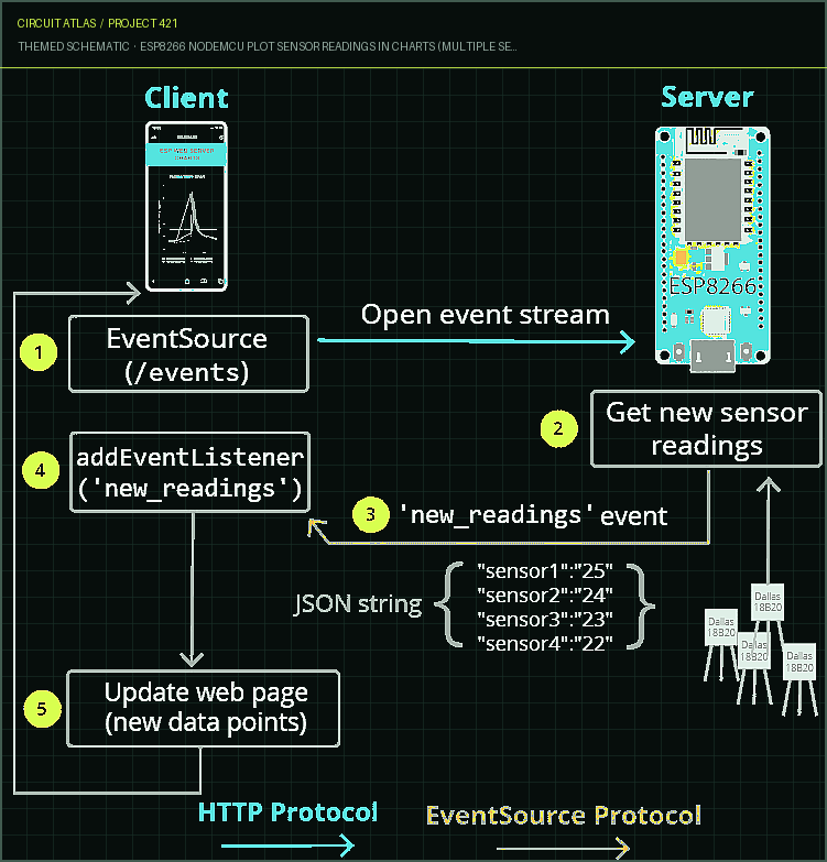
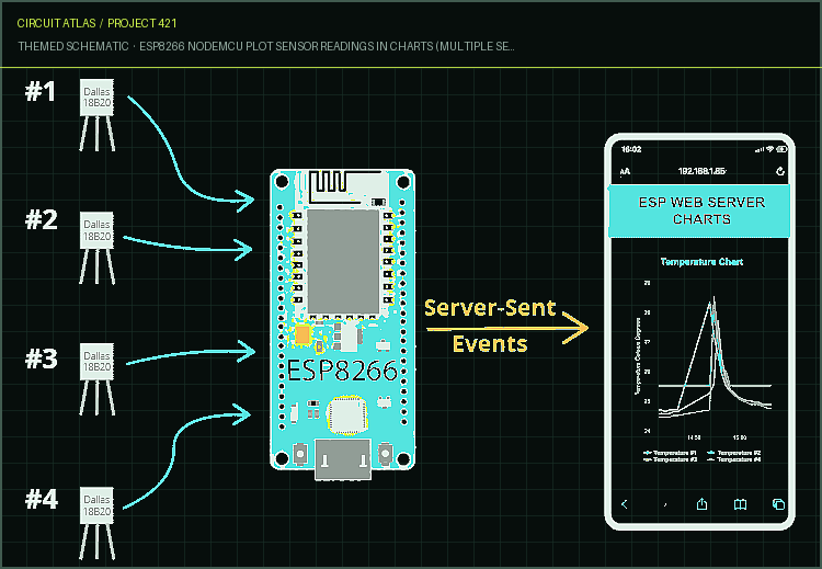
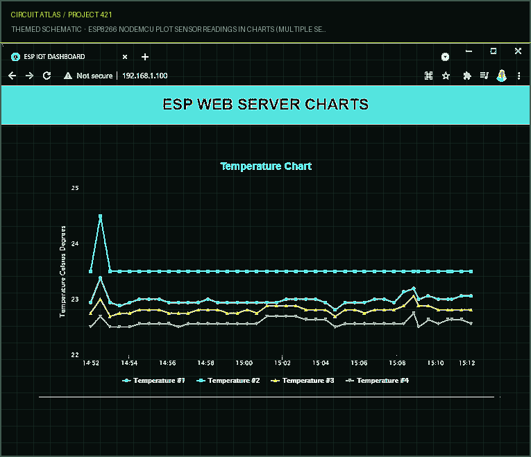
Project build noteThis project will build a web server with the ESP8266 NodeMCU board. The web server will display temperature readings from four DS18B20 temperature sensors on the same chart; the chart will have multiple series. The chart can show a maximum of forty data points for each series, and it refreshes itself with fresh data every thirty seconds. These values can be changed in your code as you see fit. DS18B20 Temperature Sensor The DS18B20 temperature sensor is a digital temperature sensor that only requires a single wire to operate. This indicates that only a single data line is necessary in order to successfully communicate with your microcontroller.
Because every sensor has its own one-of-a-kind 64-bit serial number, it is possible to connect multiple sensors to the same GPIO, which is exactly what we're going to do in this tutorial. Find out more information regarding
the DS18B20 temperature sensor here
Project build noteServer-Sent Events Server-Sent Events are used to ensure that the readings on the website are kept up to date automatically (SSE). Those files that have been saved on the filesystem (LittleFS)
The HTML, CSS, and JavaScript files that will be used to construct the web page will be saved on the filesystem of the board. This will ensure that our project is better organized and easier to comprehend (LittleFS).
Components Required
Project build noteESP8266 (read Best ESP8266 development boards) 4x DS18B20 temperature sensor (one or multiple sensors), in a water-resistant version 4.7k Ohm resistor A set of jumper wires Breadboard Prerequisites Before moving on with the project, you must first ensure that all of the prerequisites outlined in this section have been met.
1. Open the Arduino Software and Install the ESP8266 Board Using Arduino IDE, we'll write some code for the ESP8266. Therefore, the ESP8266 add-on component needs to be installed on your system. 2. Filesystem Uploader Plugin We will be utilising a plugin for the Arduino IDE known as the LittleFS Filesystem uploader in order to upload the HTML, CSS, and JavaScript files to the flash memory (LittleFS) of the ESP8266. 3. Installing Libraries You will need to install the following libraries in order to construct this project: OneWire, which was developed by Paul Stoffregen and is managed by the Arduino Library Manager; DallasTemperature, which is also managed by the Arduino Library Manager; the Arduino JSON library, which was developed by Arduino and is currently at version 0.1.0 (Arduino Library Manager) ESPAsyncWebServer (.zip folder); ESPAsyncTCP (.zip folder). You will need to use the Arduino Library Manager in order to install the first two libraries. Find the library's name by going to Sketch > Include Library > Manage Libraries and searching for it there. Due to the fact that the ESPAsyncWebServer and AsynTCP libraries cannot be installed using the Arduino Library Manager, it is necessary for you to manually copy the library files into the folder designated for Arduino Installation Libraries. Alternately, you can select the libraries you just downloaded by going to the Sketch menu in your Arduino IDE, selecting the Include Library option, and then clicking the Add.zip Library button. Library Installation (VS Code + PlatformIO)
If you are using PlatformIO to write code for the ESP8266, you need to add the following lines to the platformio.ini file in order to include the libraries (you should also change the speed of the Serial Monitor to 115200): You can use three or two DS18B20 sensors if you don't have enough of them to use all four. Alternately, you can also use other sensors (though doing so will require you to modify the code), as well as data from any other source (for instance, sensor readings received via MQTT, ESP-NOW, or random values—to experiment with this project...)
Schematic Diagram
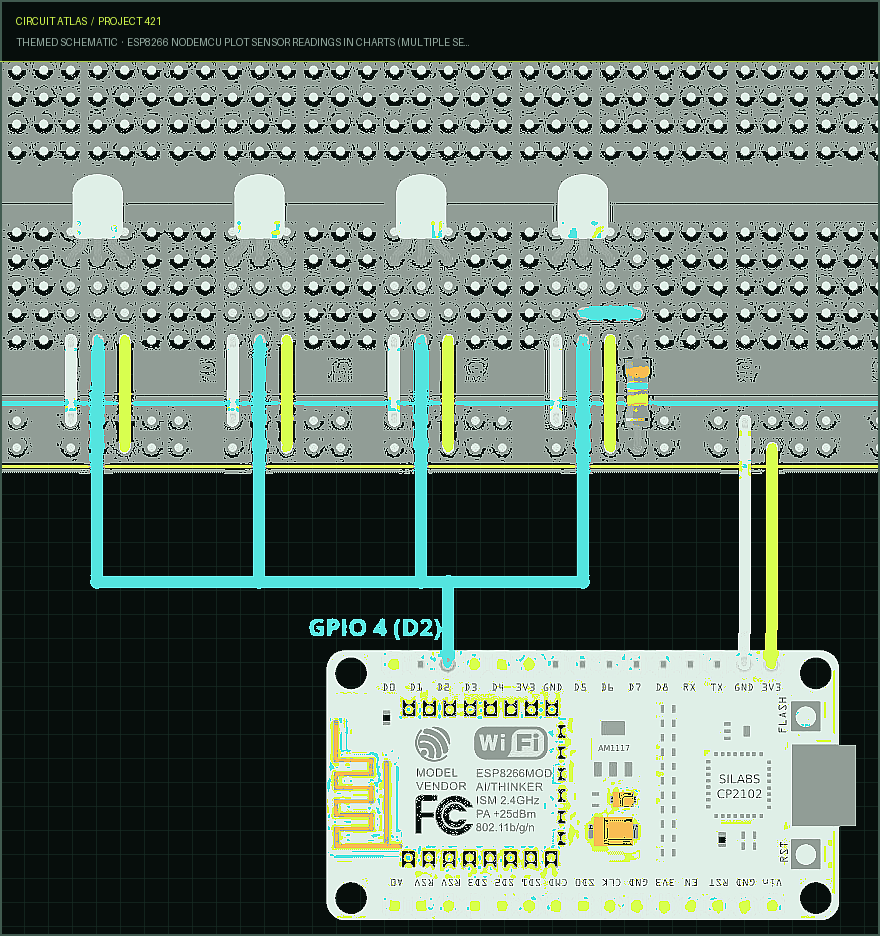
Project build noteConnect four DS18B20 sensors to your board using the wires provided.
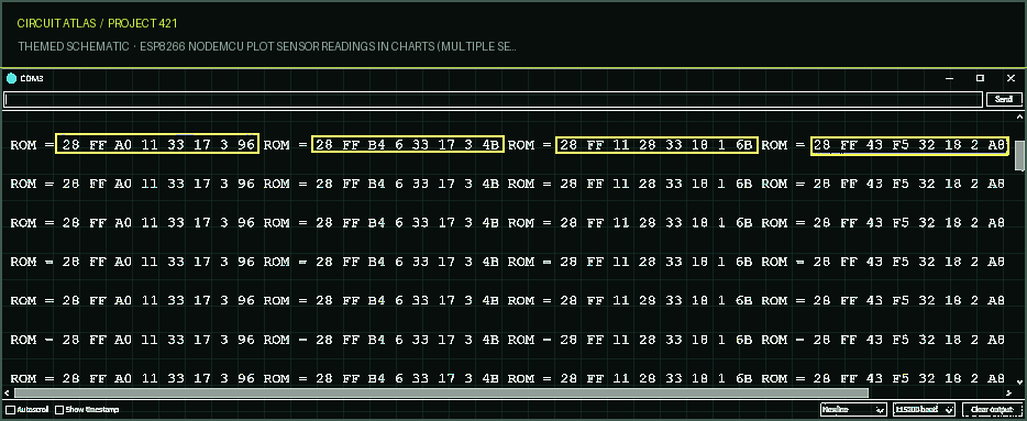
Finding Out the Addresses of the DS18B20 Sensors A unique serial number is allotted to each individual DS18B20 temperature sensor. To begin, you will need to locate that number so that you can label each sensor appropriately. You need to do this so that you will later be able to identify the temperature sensor from which you are reading the value. Wire only one sensor at a time to determine its address (or add a new sensor one by one), and repeat this process until you are able to recognize each
device based on its address. After that, you will be able to attach a physical label to every sensor. After opening the Serial Monitor with a baud rate of 115200 and pressing the RST/EN button found on the circuit board, you should see something similar to the following (but with different addresses): To enable you to copy the addresses, uncheck the box labelled "Autoscroll" in the options menu. In our
particular circumstance, we have the following addresses
Project build noteSensor 1: 28 FF A0 11 33 17 3 96 Sensor 2: 28 FF B4 6 33 17 3 4B Sensor 3: 28 FF 11 28 33 18 1 6B Sensor 4: 28 FF 43 F5 32 18 2 A8
Demonstration
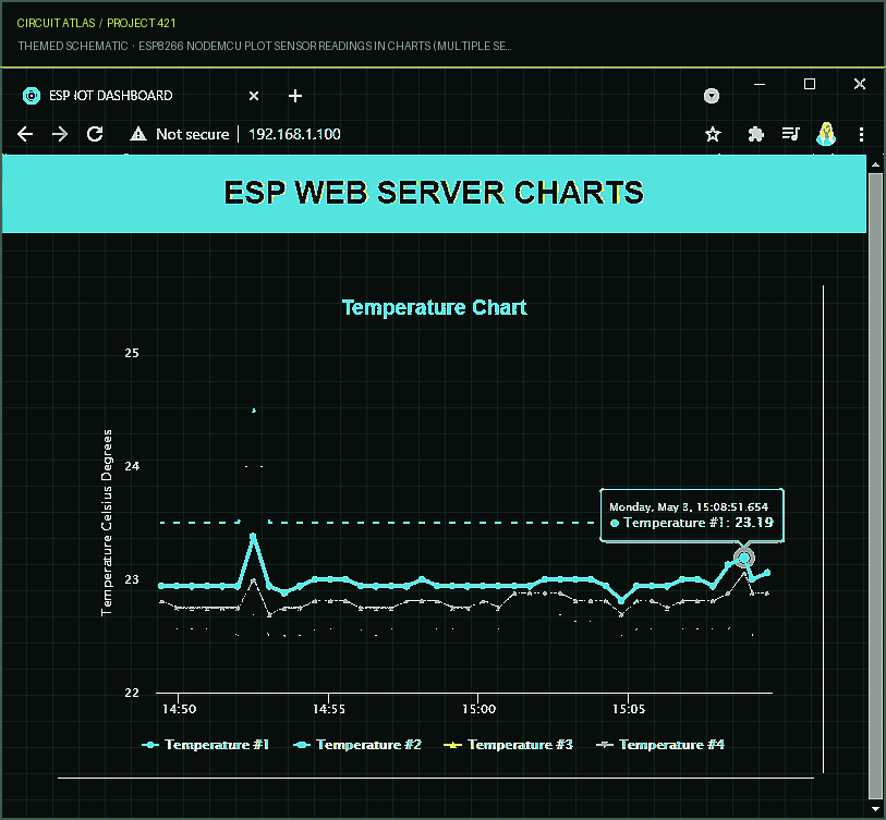
Project build noteLaunch your web browser, then type the ESP8266's IP address into the address bar. It is recommended that you gain access to the web page that displays the sensor readings. Please be patient while it collects some data points and wait some time. You can select a point to view its value as well as the timestamp it was last updated.
Wrapping Up You have learned how to make charts with multiple series to display temperature from various DS18B20 sensors from this project. You have the ability to customize this project to generate any number of charts and series you desire, as well as plot data from any other sensors or sources.
You built ESP8266 NodeMCU Plot Sensor Readings in Charts (Multiple Series).
You followed the full workflow from understanding the mission to testing the finished project. That is a real engineering achievement - well done.
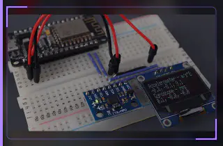
ESP8266 NodeMCU Integrated with MPU-6050 Accelerometer, Gyroscope, and Temperature Sensor (Arduino)
Ready to reuse what you learned in another project from the same track?
Start this project →