ESP8266 Voltage Regulator (LiPo and Li-ion Batteries)
435.ESP8266 Voltage Regulator (LiPo and Li-ion Batteries) Following the steps in this project will allow you to construct a voltage regulator for the ESP8266 that is compatible with both…
Know the mission before touching a wire.
Understand what you are making, prepare the right tools, and make the workbench safe.
Project details
ESP8266 Voltage Regulator (LiPo and Li-ion Batteries) is a iot project. 435.ESP8266 Voltage Regulator (LiPo and Li-ion Batteries) Following the steps in this project will allow you to construct a voltage regulator for the ESP8266 that is compatible with both…
- Source pages
- 1065-1073
- Named parts
- 6
- Build goal
- Working, tested prototype
Tools you need
- Digital multimeter
- Wire stripper and side cutters
- Soldering iron with a fine tip
- Current-limited bench supply
- Computer with a data-capable USB cable
Use eye protection, good lighting, and a clean insulated surface throughout the build.
Safety precautions
- Disconnect every power source before changing a connection.
- Check component polarity, pinout, and supply voltage twice.
- Use a current limit for the first power-up.
- This project may involve hazardous voltage. Work only with qualified supervision and proper isolation.
Gather, identify, and understand every part.
Use the standardized inventory, then open What's this? to learn each part's role, advantages, limitations, handling, and specifications.
What's this?Image, role, pros, cons, handling & specifications
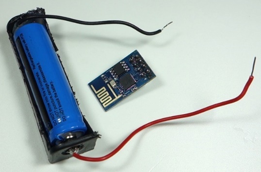
Lithium-ion or lithium-polymer batteries, along with a battery holder
A power component supplies, converts, stores, or regulates energy for the project.
What it does hereIt must provide the documented voltage, polarity, isolation, and sufficient current safely.
Buy / compare this part ↗Advantages
- Stable power improves reliability
- Current limiting protects first tests
- Regulation reduces resets and noise
Limitations
- Wrong polarity can cause immediate damage
- Underrated parts overheat
- Mains circuits require qualified supervision
Handling
- Measure output before connection
- Use a fuse or current limit
- Insulate exposed conductors
Specifications to verify
- Use the exact model, value, package, and rating listed for Lithium-ion or lithium-polymer batteries, along with a battery holder; similar-looking parts are not always interchangeable.
- Confirm input/output voltage, current, polarity, connector, isolation, and thermal rating.
What's this?Image, role, pros, cons, handling & specifications
Low-dropout regulator, also known as an LDO (MCP1700-3302E)
A power component supplies, converts, stores, or regulates energy for the project.
What it does hereIt must provide the documented voltage, polarity, isolation, and sufficient current safely.
Buy / compare this part ↗Advantages
- Stable power improves reliability
- Current limiting protects first tests
- Regulation reduces resets and noise
Limitations
- Wrong polarity can cause immediate damage
- Underrated parts overheat
- Mains circuits require qualified supervision
Handling
- Measure output before connection
- Use a fuse or current limit
- Insulate exposed conductors
Specifications to verify
- Use the exact model, value, package, and rating listed for Low-dropout regulator, also known as an LDO (MCP1700-3302E); similar-looking parts are not always interchangeable.
- Confirm input/output voltage, current, polarity, connector, isolation, and thermal rating.
What's this?Image, role, pros, cons, handling & specifications
 PASSIVE LEARNING VIEW
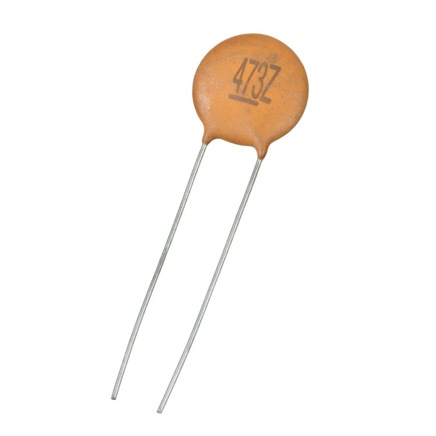
uF electrolytic capacitor 100nF ceramic capacitor
A passive component sets current, voltage, timing, filtering, or signal behaviour without adding gain.
What it does hereIts exact value and tolerance determine how the surrounding stage behaves.
Buy / compare this part ↗Advantages
- Simple and dependable
- Low cost
- Easy to measure before installation
Limitations
- A wrong value can stop or damage the circuit
- Ratings must not be exceeded
- Polarized parts require correct orientation
Handling
- Measure unclear values
- Observe capacitor polarity
- Avoid overheating leads while soldering
Specifications to verify
- Use the exact model, value, package, and rating listed for uF electrolytic capacitor 100nF ceramic capacitor; similar-looking parts are not always interchangeable.
- Confirm value, tolerance, power or voltage rating, polarity, and package size.
What's this?Image, role, pros, cons, handling & specifications
 PASSIVE LEARNING VIEW
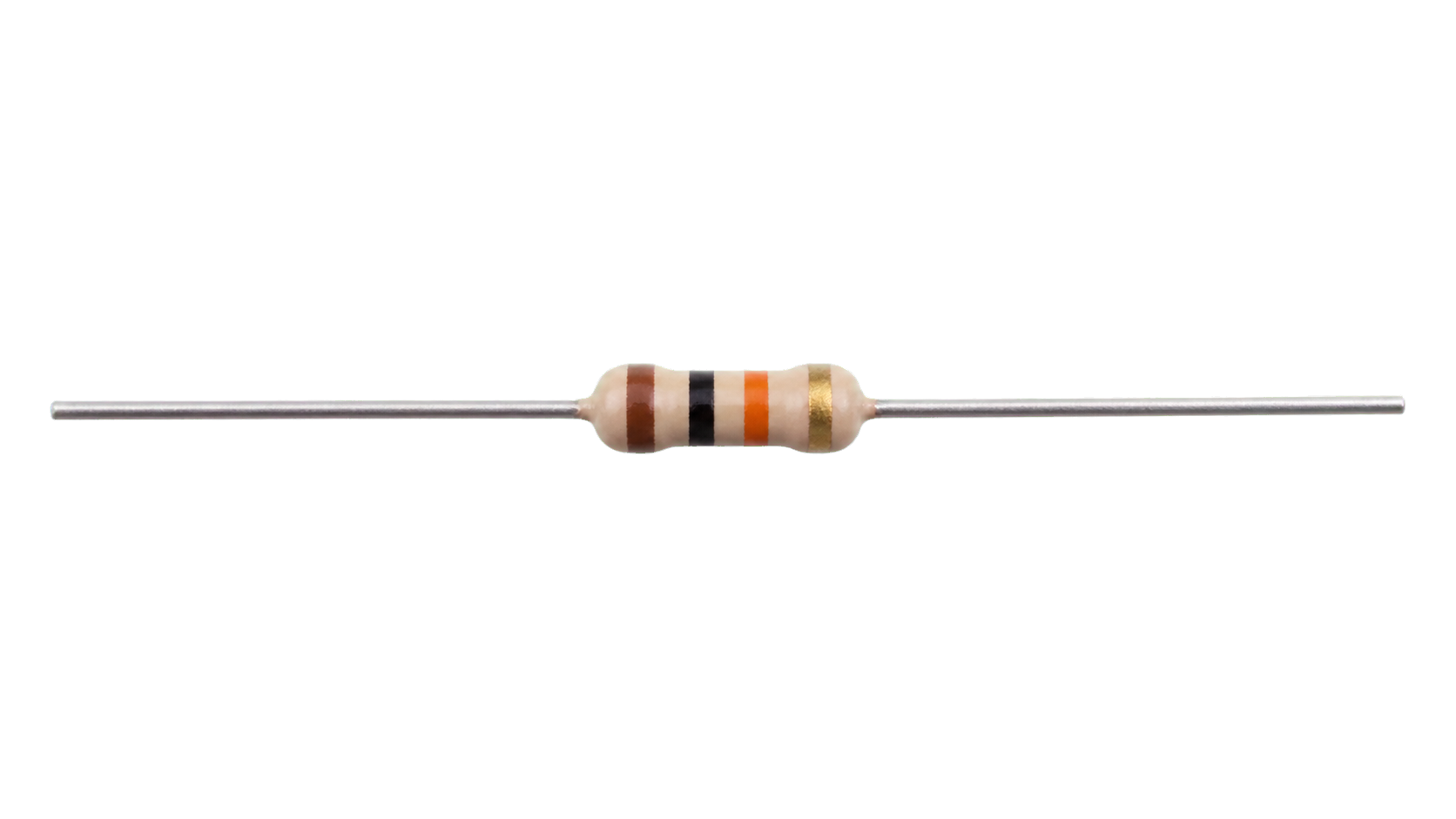
Pushbutton 10k Ohm resistor
A passive component sets current, voltage, timing, filtering, or signal behaviour without adding gain.
What it does hereIts exact value and tolerance determine how the surrounding stage behaves.
Buy / compare this part ↗Advantages
- Simple and dependable
- Low cost
- Easy to measure before installation
Limitations
- A wrong value can stop or damage the circuit
- Ratings must not be exceeded
- Polarized parts require correct orientation
Handling
- Measure unclear values
- Observe capacitor polarity
- Avoid overheating leads while soldering
Specifications to verify
- Use the exact model, value, package, and rating listed for Pushbutton 10k Ohm resistor; similar-looking parts are not always interchangeable.
- Confirm value, tolerance, power or voltage rating, polarity, and package size.
What's this?Image, role, pros, cons, handling & specifications
For more information on the ESP-01, see Best ESP8266 Wi-Fi
A programmable controller that reads inputs, makes decisions, and drives the project's outputs.
What it does hereIt is the control centre and must use the documented board, pin map, supply, and logic level.
Buy / compare this part ↗Advantages
- Reprogrammable and reusable
- Large learning ecosystem
- Complex behaviour remains changeable
Limitations
- GPIO voltage and current are limited
- Some pins affect boot or communication
- Loads normally need a driver
Handling
- Disconnect power before rewiring
- Avoid static discharge
- Never power motors, relays, or pumps directly from GPIO
Specifications to verify
- Use the exact model, value, package, and rating listed for For more information on the ESP-01, see Best ESP8266 Wi-Fi; similar-looking parts are not always interchangeable.
- Confirm operating voltage, logic level, pinout, memory, USB interface, and maximum GPIO current.
What's this?Image, role, pros, cons, handling & specifications
A set of jumper wires
A named project component whose exact role is defined by the source circuit and build guide.
What it does hereIt performs a documented electrical, control, interface, or construction function in this project.
Buy / compare this part ↗Advantages
- Selected for this project
- Can be checked independently
- Supports modular troubleshooting
Limitations
- Substitutes may differ
- Generic names can hide variants
- Pinouts and ratings vary
Handling
- Compare the received part with the source
- Keep it labelled
- Do not force connectors or adjusters
Specifications to verify
- Use the exact model, value, package, and rating listed for A set of jumper wires; similar-looking parts are not always interchangeable.
- Confirm dimensions, ratings, connection method, polarity, and environmental limits.
Connect one verified path at a time.
Explore the named components and standardized signal flow, then use Source Check to verify exact physical pins, values, and topology before applying power.
Trace this circuit.
ESP8266 Voltage Regulator (LiPo and Li-ion Batteries): interactive parts, standardized terminals, responsive anchored wires, student explanations, and the original circuit reference in one shared system.
Trace before wiring
Follow power, ground, inputs, processing, and outputs in that order. Never guess a pin from package shape alone.
Connect with power off
Make short, labelled connections and share a common ground only where the schematic requires it.
Inspect every joint
Check continuity, polarity, adjacent shorts, and loose connections before the first power-up.
Open all source diagrams and build views 6 visuals
Confirm the hardware-only control path.
This project does not include firmware in the source. The circuit itself provides the required behaviour.
How to connect
- Match every controller label to the circuit view and source pin map.
- Join grounds before signal wires when separate low-voltage supplies are used.
- Keep motors, relays, pumps, and other loads on a suitable driver and external supply.
Common mistakes
Reversed VCC/GND, board-label versus GPIO-number confusion, missing common ground, and charge-only USB cables.
Troubleshoot
Disconnect loads, continuity-test one path at a time, then test with a current limit.
Software preparation
No IDE, board package, library, or firmware upload is required for this project.
If you add a programmable controller as an extension, document its pin map separately.
How to upload code
The original design is implemented entirely in hardware, so proceed after verifying the circuit and supply.
Assemble, deploy, test, and troubleshoot.
Use the complete source notes in build order, then pass the final checks before calling the project finished.
Build in functional stages
- Power and regulation
- Controller or processing stage
- Inputs and sensors
- Outputs and loads
- Enclosure and strain relief
Power up safely
- Inspect unpowered continuity first
- Apply the lowest safe current limit
- Measure supply rails before signals
- Add one load at a time
- Record expected and actual results
Work from simple to complex
- Confirm power, ground, polarity, and orientation
- Compare each pin with the source
- Test inputs separately from outputs
- Replace only one variable at a time
- Power off before every correction
Follow the documented instructions.
These notes come from this project's source and remain in their original order.
Project overview
Project build note435.ESP8266 Voltage Regulator (LiPo and Li-ion Batteries) Following the steps in this project will allow you to construct a voltage regulator for the ESP8266 that is compatible with both LiPo and Li-ion batteries.
ESP8266 power consumption It is common knowledge that the ESP8266 consumes an excessive amount of power when working in a Wi-Fi environment. It has a power consumption range of 50 mA to 170 mA. Therefore, the use of a battery with it is not ideal for a great number of applications. If you want to avoid having to worry about power consumption or charging batteries, the best option is to make use of an adapter for power that is connected to the mains voltage. ESP8266 powered by lithium polymer and lithium-ion batteries Nevertheless, utilizing the ESP8266 with rechargeable LiPo batteries is an excellent solution for certain ESP8266 projects, such as those that make use of Deep Sleep or do not require a continuous Wi-Fi connection. Because it
has fewer components already on board, the ESP-01 variant is the board that is recommended for use with applications that are powered by a battery. Because it contains fewer components on board, the ESP-01 variant is the board that is recommended for use with applications that are powered by a battery. Because they contain additional components such as resistors, capacitors, chips, and so on, boards such as the ESP-12 NodeMCU consume a greater amount of power. we'll show you how to power the ESP8266 with LiPo batteries because those are the most readily available type of batteries to use in this scenario. This project is not about the various kinds of batteries, and I won't even attempt to explain how LiPo battery’s function. I'll just provide you with the information you need to finish the circuit that has been presented... LiPo/Li-ion batteries fully charged
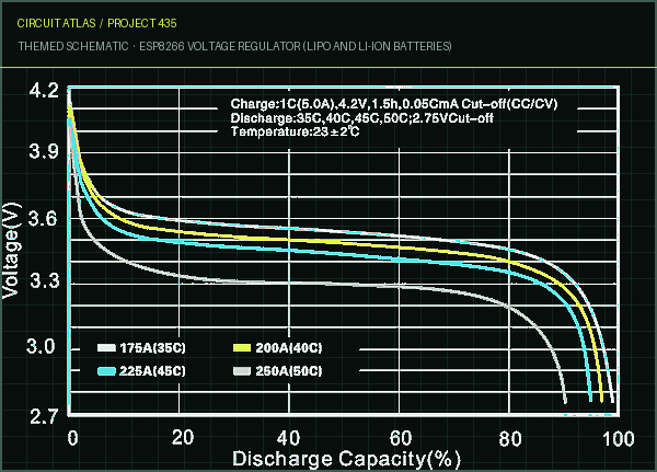
When fully charged, LiPo/Li-ion batteries can be recharged using the appropriate charger, and when they do so, they produce an output voltage of approximately 4.2V. It is recommended that the ESP be run at 3.3V, but the device is capable of functioning with voltages ranging from 3V to 3.6V. Because of this, you won't be able to connect a LiPo battery straight to an ESP8266; instead, you'll need to use a voltage regulator. Typical Linear Voltage Regulator
It is not a good idea to attempt to reduce the voltage from 4.2V to 3.3V by utilizing a standard linear voltage regulator. For instance, because it has a high cutoff voltage, your voltage regulator will stop functioning if the battery discharges all the way down to 3.7 volts. Low-dropout or LDO Regulator When working with batteries, you need to use a low-dropout regulator, also known as an LDO regulator, so that you can drop the voltage in an efficient manner. This type of regulator can also regulate the output voltage. A low dropout voltage ensures that the device will continue to function normally even if the battery is only producing 3.4V of power. It is important to keep in mind that the LiPo battery should never be completely drained because doing so can cause damage to the battery or reduce the battery's lifespan. After doing some research on LDOs, I found a few other organizations that are viable options. The MCP1700-3302E is without a doubt one of the finest LDOs that I've come across. It is not very big, and it resembles a transistor in appearance. There is also another viable option available, which is the HT7333-A. Other good alternatives include any LDO that has parameters that are comparable to those detailed in the datasheet that can be found below. Your LDO ought to
have comparable specifications with regard to the following
Project build noteOutput voltage (3.3V) Quiescent current (~1.6uA) Output current (~250mA) Low-dropout voltage (~178mV) ESP8266 Circuit with a Li-ion Battery and LDO
Part Required
Project build noteIn order to design the voltage regulator for the ESP-01, you will need the
following components
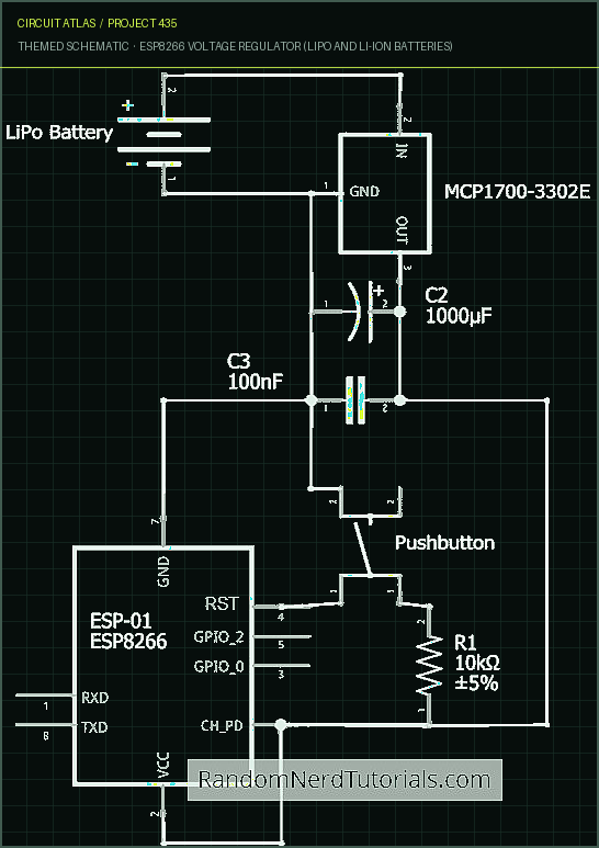
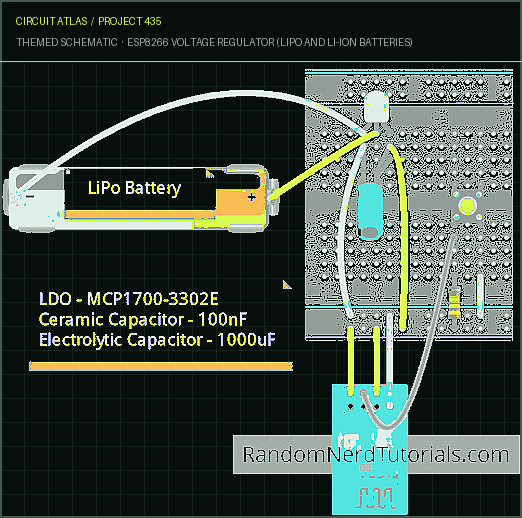
Project build noteLithium-ion or lithium-polymer batteries, along with a battery holder Low-dropout regulator, also known as an LDO (MCP1700-3302E) 1000uF electrolytic capacitor 100nF ceramic capacitor Pushbutton 10k Ohm resistor For more information on the ESP-01, see Best ESP8266 Wi-Fi Development Boards. Breadboard A set of jumper wires If you want to design your own voltage regulator circuit, take a look at the diagram that is provided in the next page. The pushbutton is connected to the RESET pin of the ESP-01. Although it is not required for this specific project, it will come in handy for a future project.
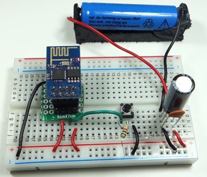
Here’s the final circuit
Project build noteAbout the capacitors In order to smooth out the peaks in the voltage, the LDOs should each have a ceramic capacitor and an electrolytic capacitor connected in parallel to GND and Vout. Your ESP8266 will not experience any unexpected resets or unstable behavior as a result of the capacitors.
Testing
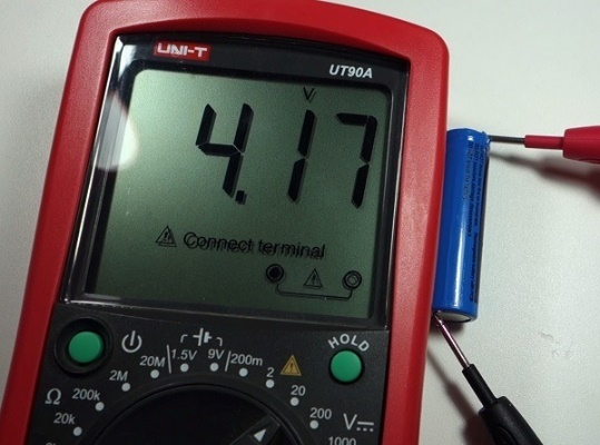
Project build noteLet's give the circuit some power and see how it performs. When you measure the Vin voltage of the LiPo battery with a multimeter, you can see that it outputs approximately 4.2V because the battery is currently at its maximum capacity and has been fully charged. Let's start by putting the probe of the multimeter on the Vout. At this time, the multimeter is measuring somewhere around 3.3V, which is the voltage that is recommended to supply power to the ESP8266.
Voltage regulator The following is an example of a popular design for the voltage regulator on the ESP8266: After soldering the capacitors to the LDO, you will have created a voltage regulator that has a small form factor and can be easily incorporated into your projects as a result. I have high hopes that this guide was helpful. This idea will be of great assistance in the operation of future projects. To that end, we offer our sincere appreciation for your participation in this endeavor. After gaining an understanding of the concepts presented in this project, you will be able to modify it to control virtually anything you want by utilizing the Nextion display interface and Node-RED.
You built ESP8266 Voltage Regulator (LiPo and Li-ion Batteries).
You followed the full workflow from understanding the mission to testing the finished project. That is a real engineering achievement - well done.
ESP8266 Weather Forecaster
Ready to reuse what you learned in another project from the same track?
Start this project →