The ESP8266 is controlled by an Android app (MIT App Inventor)
439.The ESP8266 is controlled by an Android app (MIT App Inventor) In this project, you will create an Android app that allows you to control the ESP8266 GPIOs using the MIT App Inventor…
Know the mission before touching a wire.
Understand what you are making, prepare the right tools, and make the workbench safe.
Project details
The ESP8266 is controlled by an Android app (MIT App Inventor) is a iot project. 439.The ESP8266 is controlled by an Android app (MIT App Inventor) In this project, you will create an Android app that allows you to control the ESP8266 GPIOs using the MIT App Inventor…
- Source pages
- 1088-1095
- Named parts
- 6
- Build goal
- Working, tested prototype
Tools you need
- Digital multimeter
- Wire stripper and side cutters
- Soldering iron with a fine tip
- Current-limited bench supply
- Computer with a data-capable USB cable
Use eye protection, good lighting, and a clean insulated surface throughout the build.
Safety precautions
- Disconnect every power source before changing a connection.
- Check component polarity, pinout, and supply voltage twice.
- Use a current limit for the first power-up.
- Keep liquids, loose metal, and uninsulated wires away from the bench.
Gather, identify, and understand every part.
Use the standardized inventory, then open What's this? to learn each part's role, advantages, limitations, handling, and specifications.
What's this?Image, role, pros, cons, handling & specifications
x ESP8266 (for more information, see the Best ESP8266 Wi-Fi
A programmable controller that reads inputs, makes decisions, and drives the project's outputs.
What it does hereIt is the control centre and must use the documented board, pin map, supply, and logic level.
Buy / compare this part ↗Advantages
- Reprogrammable and reusable
- Large learning ecosystem
- Complex behaviour remains changeable
Limitations
- GPIO voltage and current are limited
- Some pins affect boot or communication
- Loads normally need a driver
Handling
- Disconnect power before rewiring
- Avoid static discharge
- Never power motors, relays, or pumps directly from GPIO
Specifications to verify
- Use the exact model, value, package, and rating listed for x ESP8266 (for more information, see the Best ESP8266 Wi-Fi; similar-looking parts are not always interchangeable.
- Confirm operating voltage, logic level, pinout, memory, USB interface, and maximum GPIO current.
What's this?Image, role, pros, cons, handling & specifications
x FTDI programmer
A named project component whose exact role is defined by the source circuit and build guide.
What it does hereIt performs a documented electrical, control, interface, or construction function in this project.
Buy / compare this part ↗Advantages
- Selected for this project
- Can be checked independently
- Supports modular troubleshooting
Limitations
- Substitutes may differ
- Generic names can hide variants
- Pinouts and ratings vary
Handling
- Compare the received part with the source
- Keep it labelled
- Do not force connectors or adjusters
Specifications to verify
- Use the exact model, value, package, and rating listed for x FTDI programmer; similar-looking parts are not always interchangeable.
- Confirm dimensions, ratings, connection method, polarity, and environmental limits.
What's this?Image, role, pros, cons, handling & specifications
x LEDs
A named project component whose exact role is defined by the source circuit and build guide.
What it does hereIt performs a documented electrical, control, interface, or construction function in this project.
Buy / compare this part ↗Advantages
- Selected for this project
- Can be checked independently
- Supports modular troubleshooting
Limitations
- Substitutes may differ
- Generic names can hide variants
- Pinouts and ratings vary
Handling
- Compare the received part with the source
- Keep it labelled
- Do not force connectors or adjusters
Specifications to verify
- Use the exact model, value, package, and rating listed for x LEDs; similar-looking parts are not always interchangeable.
- Confirm dimensions, ratings, connection method, polarity, and environmental limits.
What's this?Image, role, pros, cons, handling & specifications
x 220Ω Resistors
A named project component whose exact role is defined by the source circuit and build guide.
What it does hereIt performs a documented electrical, control, interface, or construction function in this project.
Buy / compare this part ↗Advantages
- Selected for this project
- Can be checked independently
- Supports modular troubleshooting
Limitations
- Substitutes may differ
- Generic names can hide variants
- Pinouts and ratings vary
Handling
- Compare the received part with the source
- Keep it labelled
- Do not force connectors or adjusters
Specifications to verify
- Use the exact model, value, package, and rating listed for x 220Ω Resistors; similar-looking parts are not always interchangeable.
- Confirm dimensions, ratings, connection method, polarity, and environmental limits.
What's this?Image, role, pros, cons, handling & specifications
x Breadboard
A named project component whose exact role is defined by the source circuit and build guide.
What it does hereIt performs a documented electrical, control, interface, or construction function in this project.
Buy / compare this part ↗Advantages
- Selected for this project
- Can be checked independently
- Supports modular troubleshooting
Limitations
- Substitutes may differ
- Generic names can hide variants
- Pinouts and ratings vary
Handling
- Compare the received part with the source
- Keep it labelled
- Do not force connectors or adjusters
Specifications to verify
- Use the exact model, value, package, and rating listed for x Breadboard; similar-looking parts are not always interchangeable.
- Confirm dimensions, ratings, connection method, polarity, and environmental limits.
What's this?Image, role, pros, cons, handling & specifications
x Android Phone
A named project component whose exact role is defined by the source circuit and build guide.
What it does hereIt performs a documented electrical, control, interface, or construction function in this project.
Buy / compare this part ↗Advantages
- Selected for this project
- Can be checked independently
- Supports modular troubleshooting
Limitations
- Substitutes may differ
- Generic names can hide variants
- Pinouts and ratings vary
Handling
- Compare the received part with the source
- Keep it labelled
- Do not force connectors or adjusters
Specifications to verify
- Use the exact model, value, package, and rating listed for x Android Phone; similar-looking parts are not always interchangeable.
- Confirm dimensions, ratings, connection method, polarity, and environmental limits.
Connect one verified path at a time.
Explore the named components and standardized signal flow, then use Source Check to verify exact physical pins, values, and topology before applying power.
Trace this circuit.
The ESP8266 is controlled by an Android app (MIT App Inventor): interactive parts, standardized terminals, responsive anchored wires, student explanations, and the original circuit reference in one shared system.
Trace before wiring
Follow power, ground, inputs, processing, and outputs in that order. Never guess a pin from package shape alone.
Connect with power off
Make short, labelled connections and share a common ground only where the schematic requires it.
Inspect every joint
Check continuity, polarity, adjacent shorts, and loose connections before the first power-up.
Open all source diagrams and build views 5 visuals
Confirm the hardware-only control path.
This project does not include firmware in the source. The circuit itself provides the required behaviour.
How to connect
- Match every controller label to the circuit view and source pin map.
- Join grounds before signal wires when separate low-voltage supplies are used.
- Keep motors, relays, pumps, and other loads on a suitable driver and external supply.
Common mistakes
Reversed VCC/GND, board-label versus GPIO-number confusion, missing common ground, and charge-only USB cables.
Troubleshoot
Disconnect loads, continuity-test one path at a time, then test with a current limit.
Software preparation
No IDE, board package, library, or firmware upload is required for this project.
If you add a programmable controller as an extension, document its pin map separately.
How to upload code
The original design is implemented entirely in hardware, so proceed after verifying the circuit and supply.
Assemble, deploy, test, and troubleshoot.
Use the complete source notes in build order, then pass the final checks before calling the project finished.
Build in functional stages
- Power and regulation
- Controller or processing stage
- Inputs and sensors
- Outputs and loads
- Enclosure and strain relief
Power up safely
- Inspect unpowered continuity first
- Apply the lowest safe current limit
- Measure supply rails before signals
- Add one load at a time
- Record expected and actual results
Work from simple to complex
- Confirm power, ground, polarity, and orientation
- Compare each pin with the source
- Test inputs separately from outputs
- Replace only one variable at a time
- Power off before every correction
Follow the documented instructions.
These notes come from this project's source and remain in their original order.
Project overview
Project build note439.The ESP8266 is controlled by an Android app (MIT App Inventor) In this project, you will create an Android app that allows you to control the ESP8266 GPIOs using the MIT App Inventor software. Flashing Your ESP with NodeMCU
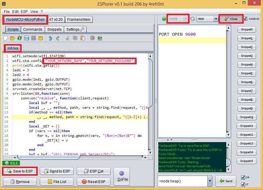
In this lesion, we will be utilizing the firmware that comes with the NodeMCU board. It is necessary for you to flash your ESP with the NodeMCU firmware. Downloading ESPlorer IDE To send commands to your ESP8266, it is highly recommended that you make use of the ESPlorer IDE, which is a program that was developed by 4refr0nt. Download ESPlorer and then extract the compressed folder. Navigate to the primary file folder. Run "ESPlorer.jar" file Launch the IDE for ESPlorer.
You should see a window that looks like the one in the figure before this one; in order to upload a Lua file, follow these instructions: Establish a connection between your computer and the FTDI programmer. Choose the appropriate port for your FTDI programmer. Use the Open/Close button. Choose the tab labeled "NodeMCU+MicroPtyhon." Make a new file and save it with the name init.lua. Click the Save to ESP button. Everything that requires your attention or requires you to make a change is highlighted in red box.
Parts Required
Project build note1x ESP8266 (for more information, see the Best ESP8266 Wi-Fi Development Boards). 1x FTDI programmer 2x LEDs 2x 220Ω Resistors 1x Breadboard 1x Android Phone
Circuit Diagram
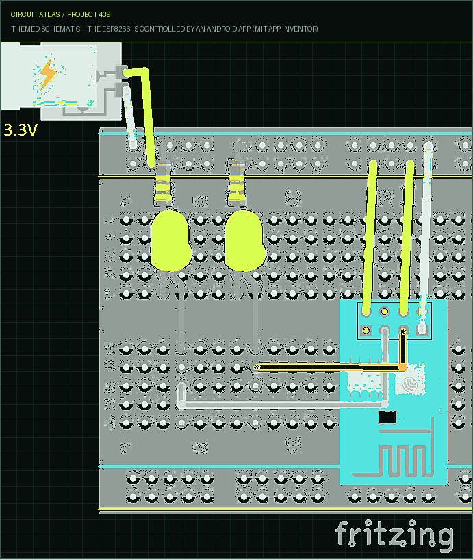
Project build noteNow, construct the circuit that controls two LEDs by following these schematics in the appropriate order.
Here’s how to edit the ESP8266 Controller app
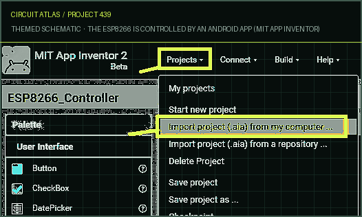
Project build noteDownload the .aia file Unzip the folder Visit the MIT App Inventor website.
To create an application, select the " Create Apps " button located in the upper right corner. Navigate to the " Projects " tab, then select "Import project (.aia)" from the drop-down menu. The IP Address of Your ESP When you restart your ESP8266, the IP address of the ESP will be printed in the serial monitor. Keep that IP address in mind for when you need it in the future. Regarding myself, the IP address of the ESP is 192.168.1.95. Please read this troubleshooting guide if you are having issues viewing your IP address. Creating an Android App with MIT App Inventor MIT App Inventor is a drag-and-drop software that enables you to create an Android app that is simple but fully functional in under an hour. You will be able to make changes to the app and observe the construction process once you have imported the.aia file Designer
You can make changes to the way the app appears by using the designer tab. Please feel free to make any changes you see fit to the text, the colors, the buttons, or the features.
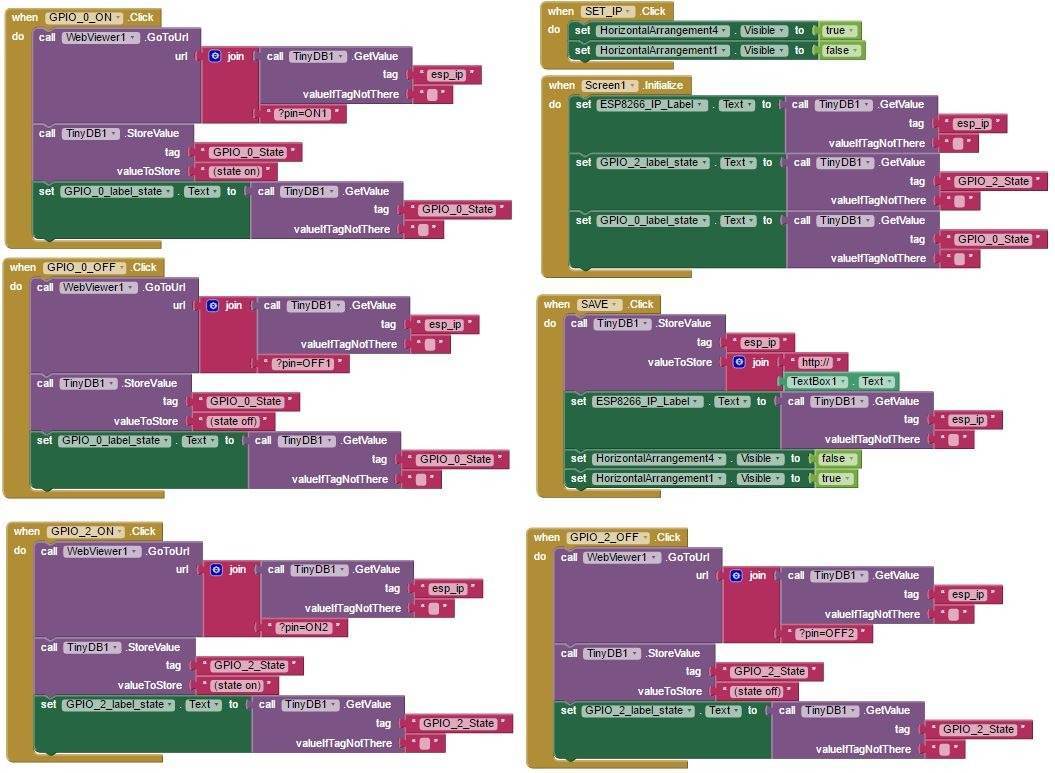
Blocks Within the blocks section of your app, you will be able to specify what each button does as well as add logic to your application. When you are finished making changes to the app, you can click the "Build" app tab to generate the.apk file and then install it on your Android device. Uploading the application that is linked below is the first step that I would
recommend you take to ensure that everything operates as it should (later you can edit the app). Installing the Android App To successfully install the default app that I've created, please follow
these instructions
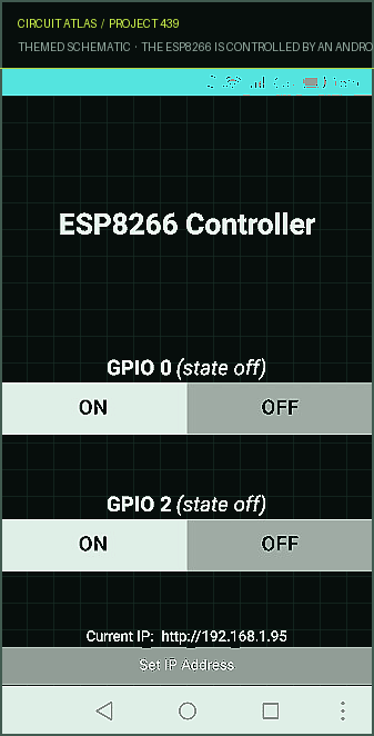
Project build notePlease visit this link in order to download the.apk file. Do not compress the folder. Transfer the.apk file to the Android device you are using. Start the installation process by opening the.apk file. When you first open the ESP8266 Controller app, it will appear as shown in the following image. The configuration couldn't be simpler. Your IP address can be changed by selecting the "Set IP Address" button at the bottom of the screen and entering it (in my case 192.168.1.95). You're all set!
Developing It Further An Android application can be easily integrated with the ESP8266, as demonstrated by this simple example, which can be found here. You are free to adapt this example to fit your needs. You could add multiple screens to the application in order to control additional ESPs or add buttons in order to manage additional GPIOs.
You built The ESP8266 is controlled by an Android app (MIT App Inventor).
You followed the full workflow from understanding the mission to testing the finished project. That is a real engineering achievement - well done.
ESP8266 - Wireless Weather Station with Data Logging to Excel
Ready to reuse what you learned in another project from the same track?
Start this project →