IoT Biometric Fingerprint Attendance System using NodeMCU
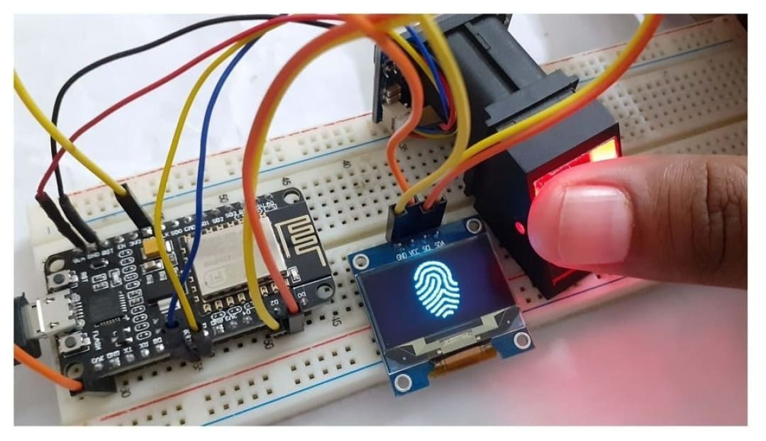
In this project, we will learn how to build an Internet of Things (IoT) based biometric fingerprint attendance system by utilizing NodeMCU ESP8266 12E, 0.96" OLED Display, and R305 Finger…
Know the mission before touching a wire.
Understand what you are making, prepare the right tools, and make the workbench safe.
Project details
IoT Biometric Fingerprint Attendance System using NodeMCU is a iot project. In this project, we will learn how to build an Internet of Things (IoT) based biometric fingerprint attendance system by utilizing NodeMCU ESP8266 12E, 0.96" OLED Display, and R305 Finger…
- Source pages
- 1235-1243
- Named parts
- 4
- Build goal
- Working, tested prototype
Tools you need
- Digital multimeter
- Wire stripper and side cutters
- Soldering iron with a fine tip
- Current-limited bench supply
- Computer with a data-capable USB cable
Use eye protection, good lighting, and a clean insulated surface throughout the build.
Safety precautions
- Disconnect every power source before changing a connection.
- Check component polarity, pinout, and supply voltage twice.
- Use a current limit for the first power-up.
- Keep liquids, loose metal, and uninsulated wires away from the bench.
Gather, identify, and understand every part.
Use the standardized inventory, then open What's this? to learn each part's role, advantages, limitations, handling, and specifications.
What's this?Image, role, pros, cons, handling & specifications
 MODULE LEARNING VIEW
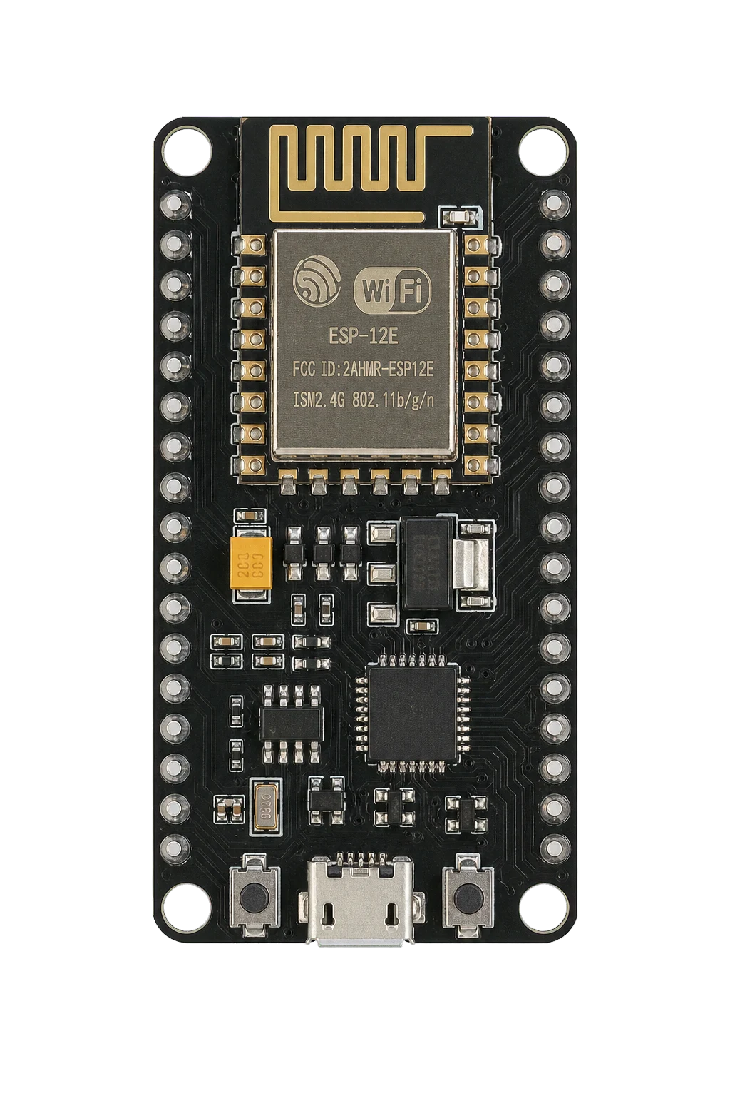
NodeMCU - ESP8266
A programmable controller that reads inputs, makes decisions, and drives the project's outputs.
What it does hereIt is the control centre and must use the documented board, pin map, supply, and logic level.
Buy / compare this part ↗Advantages
- Reprogrammable and reusable
- Large learning ecosystem
- Complex behaviour remains changeable
Limitations
- GPIO voltage and current are limited
- Some pins affect boot or communication
- Loads normally need a driver
Handling
- Disconnect power before rewiring
- Avoid static discharge
- Never power motors, relays, or pumps directly from GPIO
Specifications to verify
- Use the exact model, value, package, and rating listed for NodeMCU - ESP8266; similar-looking parts are not always interchangeable.
- Confirm operating voltage, logic level, pinout, memory, USB interface, and maximum GPIO current.
What's this?Image, role, pros, cons, handling & specifications
Fingerprint Sensor - R305/R307 Module
A sensor converts a physical condition into an electrical signal the circuit can measure.
What it does hereIt provides project input as an analogue, digital, resistive, frequency, or calibrated signal.
Buy / compare this part ↗Advantages
- Adds real-world awareness
- Can usually be tested independently
- Often supports calibration
Limitations
- Readings can drift
- Placement affects results
- Some sensors need warm-up or calibration
Handling
- Protect the sensing surface
- Observe supply voltage and polarity
- Keep signal leads away from noisy power wiring
Specifications to verify
- Use the exact model, value, package, and rating listed for Fingerprint Sensor - R305/R307 Module; similar-looking parts are not always interchangeable.
- Confirm supply range, output type, measurement range, accuracy, response time, and pin order.
What's this?Image, role, pros, cons, handling & specifications
OLED Display
An output component turns an electrical control signal into light, sound, motion, switching, or displayed information.
What it does hereIt presents the circuit result or acts on the physical world.
Buy / compare this part ↗Advantages
- Makes system state visible
- Can be tested separately
- Supports clear troubleshooting
Limitations
- Loads may exceed controller current
- Polarity or driver direction can matter
- Inductive loads create voltage spikes
Handling
- Use the documented driver stage
- Check polarity and load current
- Add flyback protection for inductive loads
Specifications to verify
- Use the exact model, value, package, and rating listed for OLED Display; similar-looking parts are not always interchangeable.
- Confirm voltage, current, polarity, interface, driver requirements, and duty cycle.
What's this?Image, role, pros, cons, handling & specifications
MAX232 - integrated circuit
A named project component whose exact role is defined by the source circuit and build guide.
What it does hereIt performs a documented electrical, control, interface, or construction function in this project.
Buy / compare this part ↗Advantages
- Selected for this project
- Can be checked independently
- Supports modular troubleshooting
Limitations
- Substitutes may differ
- Generic names can hide variants
- Pinouts and ratings vary
Handling
- Compare the received part with the source
- Keep it labelled
- Do not force connectors or adjusters
Specifications to verify
- Use the exact model, value, package, and rating listed for MAX232 - integrated circuit; similar-looking parts are not always interchangeable.
- Confirm dimensions, ratings, connection method, polarity, and environmental limits.
Connect one verified path at a time.
Explore the named components and standardized signal flow, then use Source Check to verify exact physical pins, values, and topology before applying power.
Trace this circuit.
IoT Biometric Fingerprint Attendance System using NodeMCU: interactive parts, standardized terminals, responsive anchored wires, student explanations, and the original circuit reference in one shared system.
Trace before wiring
Follow power, ground, inputs, processing, and outputs in that order. Never guess a pin from package shape alone.
Connect with power off
Make short, labelled connections and share a common ground only where the schematic requires it.
Inspect every joint
Check continuity, polarity, adjacent shorts, and loose connections before the first power-up.
Open all source diagrams and build views 4 visuals
Confirm the hardware-only control path.
This project does not include firmware in the source. The circuit itself provides the required behaviour.
How to connect
- Match every controller label to the circuit view and source pin map.
- Join grounds before signal wires when separate low-voltage supplies are used.
- Keep motors, relays, pumps, and other loads on a suitable driver and external supply.
Common mistakes
Reversed VCC/GND, board-label versus GPIO-number confusion, missing common ground, and charge-only USB cables.
Troubleshoot
Disconnect loads, continuity-test one path at a time, then test with a current limit.
Software preparation
No IDE, board package, library, or firmware upload is required for this project.
If you add a programmable controller as an extension, document its pin map separately.
How to upload code
The original design is implemented entirely in hardware, so proceed after verifying the circuit and supply.
Assemble, deploy, test, and troubleshoot.
Use the complete source notes in build order, then pass the final checks before calling the project finished.
Build in functional stages
- Power and regulation
- Controller or processing stage
- Inputs and sensors
- Outputs and loads
- Enclosure and strain relief
Power up safely
- Inspect unpowered continuity first
- Apply the lowest safe current limit
- Measure supply rails before signals
- Add one load at a time
- Record expected and actual results
Work from simple to complex
- Confirm power, ground, polarity, and orientation
- Compare each pin with the source
- Test inputs separately from outputs
- Replace only one variable at a time
- Power off before every correction
Follow the documented instructions.
These notes come from this project's source and remain in their original order.
Project overview
Project build noteIn this project, we will learn how to build an Internet of Things (IoT) based biometric fingerprint attendance system by utilizing NodeMCU ESP8266 12E, 0.96" OLED Display, and R305 Fingerprint Sensor. The project is called IoT Biometric Project. The fingerprint data from a number of different users will be gathered by an ESP8266 Wi-Fi Module, which will then transmit the data to a website via the internet. The enrolment of fingerprints is carried out on the server by making use of an R305 or R307 or any other compatible Fingerprint Sensor. Verification of fingerprints is carried out on the client by making use of the transmission of fingerprint templates over the network. The database and attendance records can be accessed through the website that is written in PHP. After logging into the website, you will have access to all of the attendance records of each user, which will include their personal information as well as the times they logged in and out. Additionally, the information can be downloaded and transferred to an Excel spreadsheet.
The traditional methods of authentication, such as RFID tags and authentication cards, both have a number of flaws; the biometric method of authentication is an immediate replacement for these traditional methods. Fingerprints, voices, and electrocardiogram (ECG) signals are all examples of biometrics that are completely unique to each individual and cannot be imitated. Real-time system implementations are made easier as a result of this. Biometric Attendance systems are systems that are frequently used in offices and schools to mark the presence of individuals. This project has a wide range of potential applications in settings such as schools and colleges as well as business organizations and offices where accurate and timely attendance marking is required. Therefore, the incorporation of the fingerprint sensor will result in an increased level of protection for the users of the system. Here, at Arduino Fingerprint Attendance System, you can follow the instructions for the basic level of the same project. GT511C3 is a fingerprint sensor that you can use in the event that you are looking for a better option that is also compact and lightweight. R305 Fingerprint Scanner Sensor Module
Introduction
Project build noteThis is a finger print sensor module equipped with a TTL UART interface, allowing for direct connections to microcontroller UART or to a PC by way of a MAX232 or USB-Serial adapter. The information about the user's fingerprints can be saved in the module, and the user can choose whether to identify the person using a 1:1 or 1: N configuration for the module. Any microcontroller, including Arduino Boards, can be directly interfaced with the fingerprint module thanks to its plug-and-play design. This optical biometric fingerprint reader is packed with great features, and it can be
embedded into a wide variety of end products such as access control systems, attendance systems, safety deposit box locking systems, and car door locking systems.
Features
Project build note1. A single chip that performs both image collection and algorithm processing, integrated together 2. The fingerprint reader is capable of secondary development and can be integrated into a wide range of final products 3. a low amount of power consumed, a low cost, a small size, and outstanding performance 4. Expert optical technology and precise manufacturing techniques for modules 5. Capturing images with a resolution of up to 500 dpi is possible when good image processing capabilities are present.
Specifications
Project build note1. The optical type of fingerprint sensor is used. 2. The lifespan of the sensor is one hundred million times 3. Static indicators are rated at 15 kilovolts 4. In the rear-view mirror: a vivid green 5. The interface is a USB port 6. 1.1/UART(TTL logical level) (TTL logical level) 7. The baud rate for RS232 communications can range anywhere from 4800 to 115200. 8. Dimension: 553221.5mm 9. Image Capture Surface 15—18 (mm)
10. Time required for verification: 0.3 seconds 9. Time required for scanning: 0.5 seconds 11. The size of the character file is 256 bytes 12. The size of the template is 512 bytes 13. Capacity for storing things: 250 14. The highest possible security level is a 5 (1,2,3,4,5). 15. False Acceptance Rate (FAR):0.0001% 16. The false rejection rate, also known as the FRR, is 0.1%. 17. Resolution 500 DPI 18. Voltage:3.6-6.0 VDC 19. Working current: 90 mA on average, with a peak of 150 mA 20. Method of Compatibility: 1: N 21. Ambient Conditions of Operation Temperature: -20 to 45° centigrade 0.96″ I2C OLED Display This is a blue OLED display module with a 0.96-inch screen. SPI and IIC protocols can be used to create an interface between the display module and any microcontroller. This image has a resolution of 128 by 64 pixels. Display board, display, and a male header with 4 pins that has been pre- soldered to the board are all included in this package. Organic Light-Emitting Diode, or OLED for short, is a self-lighting technology that is made up of a multi-layered organic film that is very thin and is sandwiched between an anode and a cathode. OLED technology, on the other hand, does not require a backlight, in contrast to LCD. It is widely acknowledged that organic light-emitting diode (OLED) technology represents the pinnacle of innovation for the next generation of flat-panel
displays and possesses a high application potential for virtually every type of display.
Component Required
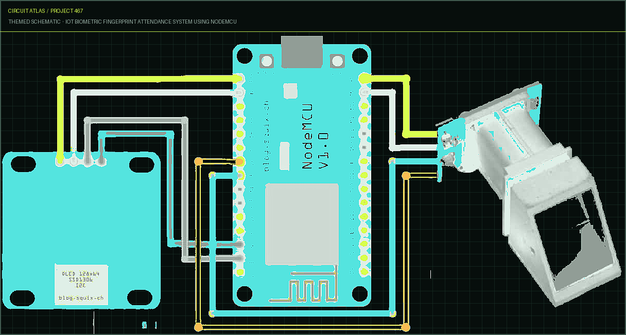
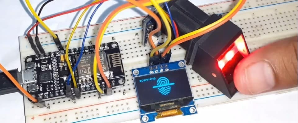
Project build noteNodeMCU - ESP8266 Fingerprint Sensor - R305/R307 Module OLED Display Connecting Wires Breadboard Circuit Diagram: IOT Based Biometric Fingerprint Attendance System The OLED Display and Fingerprint Sensor are connected to the NodeMCU ESP8266 12E Board in the manner that is depicted in the circuit diagram that was just presented. OLED Display's SDA and SCL I2C pins are connected to NodeMCU's D2 and D1 pins, respectively, so that the display can communicate over I2C. In a similar fashion, the fingerprint sensor is connected to the UART pins labeled D5 and D6. The color of the fingerprint sensor's Tx and Rx wires might be different. In my situation, the color is yellow and blue, with yellow representing treatment and blue
representing recovery. Therefore, you need to connect it by locating the appropriate color wires in order for NodeMCU to recognize the module. The 5V that is required by the R305 fingerprint sensor is drawn from the NodeMCU's Vin pins. In my experience, applying 3.3V to the sensor caused it to become inoperable. In a similar manner, connect the Vcc pin of the OLED to the 3.3V of the NodeMCU.
Setting Up the Website
Project build noteIf you already have a domain name and a server, we can help you set up a website right here. If you don't want to spend money on website management, you can use the IP address of your computer as a server to save the data locally in localhost. This is an option if you don't want to spend money. First, get Xampp by downloading and installing it. After the download and installation are finished, make a copy of the folder. Transfer the Biometric attendance Folder to the C:xampphtdocs directory . Within your computer's C drive, this is the location of the website. Results The Adafruit logo will appear on the screen during the boot process of the NodeMCU once the code has been uploaded. After that, it will attempt to establish a connection to the wireless network. Connected will appear on the screen once it has successfully established a connection. Both the Serial Monitor and the OLED Display are capable of displaying this log for your perusal.
You may now initiate the registration process for the user by using the website. The following video provides an in-depth walkthrough of the entire registration process. You can complete the registration process by watching the video provided. The EEPROM of the Fingerprint Sensor stores the user's fingerprint after it has been captured twice and stored there. It is important to keep in mind that this R305/R307 module is only capable of storing 127 fingerprints at a time. Therefore, once the fingerprints of multiple users have been saved, you will be able to begin scanning in order to register attendance. In the event that the fingerprint does not match, it will present the user with an error message. Therefore, once the fingerprints of multiple users have been saved, you will be able to begin scanning in order to register attendance. In the event that the fingerprint does not match, it will present the user with an error message. When a user who is already registered scans his finger for the first time, a welcome message will appear on the screen.
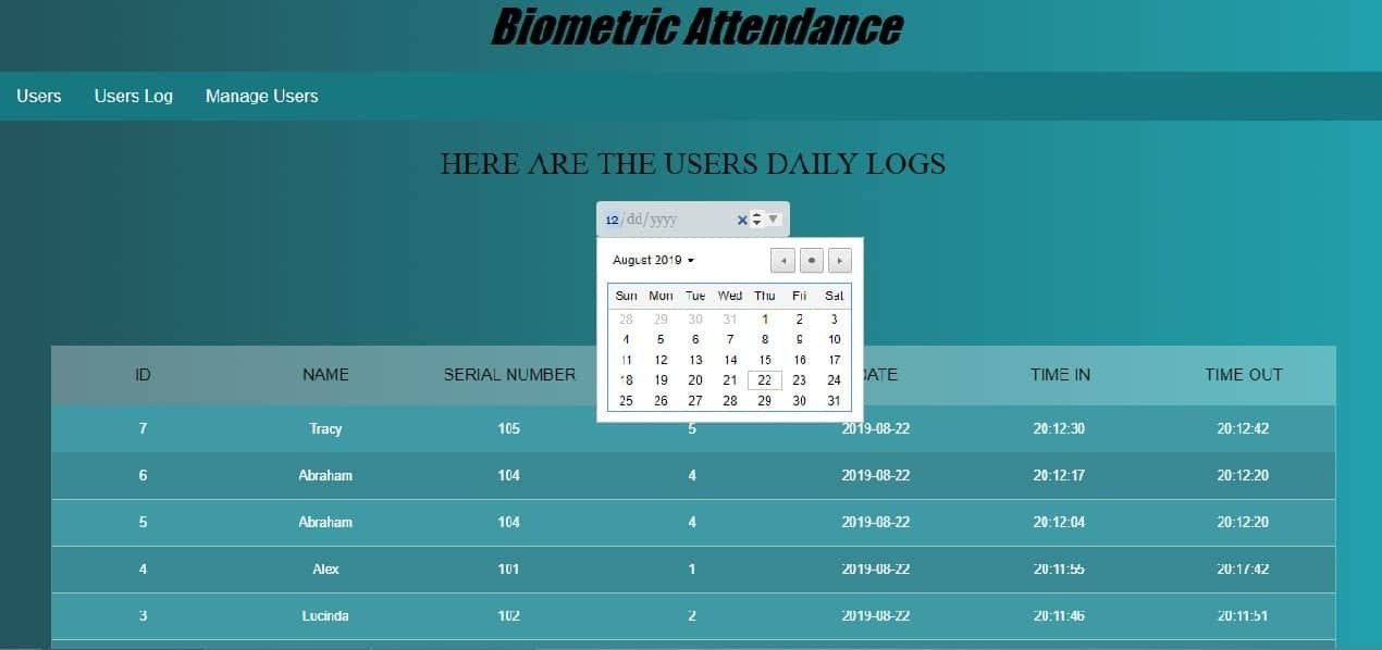
After a registered user has scanned his finger for the second time, the system will show the user the "Good-Bye" message. At long last, you are able to view all of the information pertaining to the website's users in the format shown in the image.
You built IoT Biometric Fingerprint Attendance System using NodeMCU.
You followed the full workflow from understanding the mission to testing the finished project. That is a real engineering achievement - well done.
IoT Based RFID Attendance System Using Arduino ESP8266 & Adafruit.io
Ready to reuse what you learned in another project from the same track?
Start this project →