Monitoring the power output of solar panels over the Internet of Things using ESP32 and ThingSpeak
487.Monitoring the power output of solar panels over the Internet of Things using ESP32 and ThingSpeak Solar energy is currently at the forefront of the field of renewable energy. This is…
Know the mission before touching a wire.
Understand what you are making, prepare the right tools, and make the workbench safe.
Project details
Monitoring the power output of solar panels over the Internet of Things using ESP32 and ThingSpeak is a iot project. 487.Monitoring the power output of solar panels over the Internet of Things using ESP32 and ThingSpeak Solar energy is currently at the forefront of the field of renewable energy. This is…
- Source pages
- 1367-1377
- Named parts
- 4
- Build goal
- Working, tested prototype
Tools you need
- Digital multimeter
- Wire stripper and side cutters
- Soldering iron with a fine tip
- Current-limited bench supply
- Computer with a data-capable USB cable
Use eye protection, good lighting, and a clean insulated surface throughout the build.
Safety precautions
- Disconnect every power source before changing a connection.
- Check component polarity, pinout, and supply voltage twice.
- Use a current limit for the first power-up.
- This project may involve hazardous voltage. Work only with qualified supervision and proper isolation.
Gather, identify, and understand every part.
Use the standardized inventory, then open What's this? to learn each part's role, advantages, limitations, handling, and specifications.
What's this?Image, role, pros, cons, handling & specifications
ESP32
A programmable controller that reads inputs, makes decisions, and drives the project's outputs.
What it does hereIt is the control centre and must use the documented board, pin map, supply, and logic level.
Buy / compare this part ↗Advantages
- Reprogrammable and reusable
- Large learning ecosystem
- Complex behaviour remains changeable
Limitations
- GPIO voltage and current are limited
- Some pins affect boot or communication
- Loads normally need a driver
Handling
- Disconnect power before rewiring
- Avoid static discharge
- Never power motors, relays, or pumps directly from GPIO
Specifications to verify
- Use the exact model, value, package, and rating listed for ESP32; similar-looking parts are not always interchangeable.
- Confirm operating voltage, logic level, pinout, memory, USB interface, and maximum GPIO current.
What's this?Image, role, pros, cons, handling & specifications
Potentiometer
A named project component whose exact role is defined by the source circuit and build guide.
What it does hereIt performs a documented electrical, control, interface, or construction function in this project.
Buy / compare this part ↗Advantages
- Selected for this project
- Can be checked independently
- Supports modular troubleshooting
Limitations
- Substitutes may differ
- Generic names can hide variants
- Pinouts and ratings vary
Handling
- Compare the received part with the source
- Keep it labelled
- Do not force connectors or adjusters
Specifications to verify
- Use the exact model, value, package, and rating listed for Potentiometer; similar-looking parts are not always interchangeable.
- Confirm dimensions, ratings, connection method, polarity, and environmental limits.
What's this?Image, role, pros, cons, handling & specifications
Temperature sensor
A sensor converts a physical condition into an electrical signal the circuit can measure.
What it does hereIt provides project input as an analogue, digital, resistive, frequency, or calibrated signal.
Buy / compare this part ↗Advantages
- Adds real-world awareness
- Can usually be tested independently
- Often supports calibration
Limitations
- Readings can drift
- Placement affects results
- Some sensors need warm-up or calibration
Handling
- Protect the sensing surface
- Observe supply voltage and polarity
- Keep signal leads away from noisy power wiring
Specifications to verify
- Use the exact model, value, package, and rating listed for Temperature sensor; similar-looking parts are not always interchangeable.
- Confirm supply range, output type, measurement range, accuracy, response time, and pin order.
What's this?Image, role, pros, cons, handling & specifications
MAXIMUM
A named project component whose exact role is defined by the source circuit and build guide.
What it does hereIt performs a documented electrical, control, interface, or construction function in this project.
Buy / compare this part ↗Advantages
- Selected for this project
- Can be checked independently
- Supports modular troubleshooting
Limitations
- Substitutes may differ
- Generic names can hide variants
- Pinouts and ratings vary
Handling
- Compare the received part with the source
- Keep it labelled
- Do not force connectors or adjusters
Specifications to verify
- Use the exact model, value, package, and rating listed for MAXIMUM; similar-looking parts are not always interchangeable.
- Confirm dimensions, ratings, connection method, polarity, and environmental limits.
Connect one verified path at a time.
Explore the named components and standardized signal flow, then use Source Check to verify exact physical pins, values, and topology before applying power.
Trace this circuit.
Monitoring the power output of solar panels over the Internet of Things using ESP32 and ThingSpeak: interactive parts, standardized terminals, responsive anchored wires, student explanations, and the original circuit reference in one shared system.
Trace before wiring
Follow power, ground, inputs, processing, and outputs in that order. Never guess a pin from package shape alone.
Connect with power off
Make short, labelled connections and share a common ground only where the schematic requires it.
Inspect every joint
Check continuity, polarity, adjacent shorts, and loose connections before the first power-up.
Open all source diagrams and build views 6 visuals
Confirm the hardware-only control path.
This project does not include firmware in the source. The circuit itself provides the required behaviour.
How to connect
- Match every controller label to the circuit view and source pin map.
- Join grounds before signal wires when separate low-voltage supplies are used.
- Keep motors, relays, pumps, and other loads on a suitable driver and external supply.
Common mistakes
Reversed VCC/GND, board-label versus GPIO-number confusion, missing common ground, and charge-only USB cables.
Troubleshoot
Disconnect loads, continuity-test one path at a time, then test with a current limit.
Software preparation
No IDE, board package, library, or firmware upload is required for this project.
If you add a programmable controller as an extension, document its pin map separately.
How to upload code
The original design is implemented entirely in hardware, so proceed after verifying the circuit and supply.
Assemble, deploy, test, and troubleshoot.
Use the complete source notes in build order, then pass the final checks before calling the project finished.
Build in functional stages
- Power and regulation
- Controller or processing stage
- Inputs and sensors
- Outputs and loads
- Enclosure and strain relief
Power up safely
- Inspect unpowered continuity first
- Apply the lowest safe current limit
- Measure supply rails before signals
- Add one load at a time
- Record expected and actual results
Work from simple to complex
- Confirm power, ground, polarity, and orientation
- Compare each pin with the source
- Test inputs separately from outputs
- Replace only one variable at a time
- Power off before every correction
Follow the documented instructions.
These notes come from this project's source and remain in their original order.
Project overview
Project build note487.Monitoring the power output of solar panels over the Internet of Things using ESP32 and ThingSpeak
Solar energy is currently at the forefront of the field of renewable energy. This is due to the fact that harnessing the power of the sun to generate electricity is the most straightforward and economically feasible method of generating renewable energy. When it comes to solar panels, the output power of each panel needs to be carefully monitored in order to ensure that the panels are producing the most amount of power possible. Because of this, having a monitoring system that operates in real time is essential. It is also possible to use it to monitor the power output from each panel in a large solar power plant, which assists in the identification of dust buildup. In addition to this, it eliminates the possibility of any fault circumstances occurring while the machine is running. We have constructed a few projects linked to solar energy in some of our earlier posts. These projects include a solar-powered cell phone charger and a solar inverter circuit, amongst others. If you are interested in solar power and are seeking for other projects, you can look at those.
In this project, we will be constructing an IoT-based Solar Power Monitoring System by including the MPPT-based battery charging approach, which will help to reduce the amount of time needed to charge the battery while simultaneously improving the system's efficiency. In addition, in order to make the circuit more secure, we are going to take readings of the temperature of the panel, the output voltage, and the current. In the end, the cherry on top is that we are going to employ the cloud services provided by ThingSpeak so that we may monitor the output data from any location in the world. Please be aware that the MPPT Solar Charge Controller Project, which we constructed earlier, will be continued in this project. Using the ESP32 Internet of Things development board, we are going to now monitor the output voltage, current, and power of the solar panel. How to Select the Appropriate Components for an Internet of Things- Enabled Solar Power Monitor When a solar system is equipped with a solar monitor, it is much simpler to monitor the system and identify problems should they arise. Because of this, choosing the components to go into the system becomes a highly critical element of the design process. The list of components that we made use of may be found down below. ESP32 dev board MPPT circuit (can be any solar circuit) A resistor that is shunted (for example 1 Ohm 1 watt - suitable for up to 1A of current) A battery that uses lithium (7.4v preferred). Connection to Wi-Fi that is active a sensor that can read the temperature of the solar panel
Voltage divider circuit (see the description)
Esp32 Dev Board
Project build noteIt is essential to select the appropriate type of development board in order to enable an application to work with the Internet of Things. This board must be able to process the data coming from its analog pins and transmit it using any type of connection protocol, including Wi-Fi or to a cloud server. We went with the ESP32 because it is a microcontroller that comes packed with a lot of functions but doesn't cost that much. Additionally, it has a Wi-Fi radio already installed in it, so we can connect to the internet without much difficulty using that.
Solar Circuit
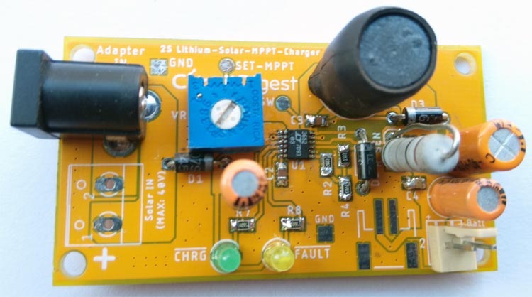
Project build noteA solar charging circuit is a circuit that receives a greater voltage from the solar panel, then transforms it down to a charging voltage in order to charge the battery in the most effective manner possible. For this project, we will be utilizing the LT3562-based MPPT Charge Controller Circuit Board that we have already developed for one of our past projects. This board was used for one of our earlier projects. But you may use any kind of solar circuit if you want to implement this Internet of Things enabling monitoring into your system. Because the circuit on this board includes Maximum Power Point Tracking (MPPT), which is advantageous for low power solar panel projects, we decided to go with it as our board of choice. Using a solar panel to charge a lithium-ion battery pack in a tiny device is an effective method.
Shunt Resistor
Project build noteAny resistor adheres to ohm's law, which states that there will be a drop in voltage proportional to the amount of current that passes through the resistor. Shunt resistors are not an exception to this rule; rather, they are utilized for the express purpose of measuring the flow of current. Choose a shunt resistor, however, that will create an acceptable level of voltage that can be measured by the microcontroller unit depending on the nominal current flow that will be going through the solar panel. This will be done depending on how much current will be going through the solar panel. However, the wattage of the resistor is also something to take into consideration as it is a vital factor. The selection of the wattage for the shunt resistor is also a critical step. The following formula can be used to compute the voltage drop that has occurred. This principle is referred to as Ohm's law.
V = I x R The voltage that will be created during 'I,' also known as the amount of current that will flow through the resistor 'R,' is denoted by the letter V. When one ampere of current passes through a resistor with an ohm rating of one, for instance, the voltage across the resistor will drop by one volt. The formula that is provided below can be used to get the wattage of the
resistor
Project build noteP=I2R Where I is the greatest amount of current that can flow through the resistor and R is the magnitude of the resistor. It is sufficient to use one watt to dissipate the power when dealing with one ampere of current and one ohm of resistance. However, this is helpful for solar panel projects that are on a smaller scale, but it is not at all ideal for applications that are related to solar grids. In such a scenario, the technique for measuring current that does not involve any intrusion into the system is the one that should be employed. In such a scenario, the current flow can be reliably measured even when measuring a very low quantity of current or a very high amount of current, because both of these current amounts are measurable.
Lithium Battery
Project build noteWhen working with solar panels, it is imperative to carefully select the lithium battery that will be used in the project. Because the microcontroller unit that is always on and continuously examines and transmits the data requires at least a hundred milliamperes of electricity for stable functioning, the battery must be replaced every few days.
When the sun is not shining because of the monsoon, the capacity of the battery should be such that it can continue to power the microcontroller for at least four to five days. From the standpoint of the battery, having a charge current that is higher than the load current is also something that is very crucial to have. It is highly unusual for someone to attach a load of 100 milliampere-seconds to a battery and then deliver a charge current that is lower than that load. If we want to err on the side of caution, we need to ensure that the charging current is at least five times higher than the load current. On the other hand, the microcontroller calls for an input voltage that is higher than the typical voltage regulator's input voltage, so the battery voltage must be higher than that. As an illustration, a lithium battery with 7.4 volts might be linked across a linear voltage regulator with either 3.3 or 5.0 volts (as linear regulator requires higher dropout voltage more than the LDO and Switching.) For our project, we utilized a battery that had a capacity of 4000 mAH and a voltage rating of 7.4 V. We utilized a regulator that operates at 5.0V and supplies the ESP32 with an adequate amount of both current and voltage.
Voltage Divider
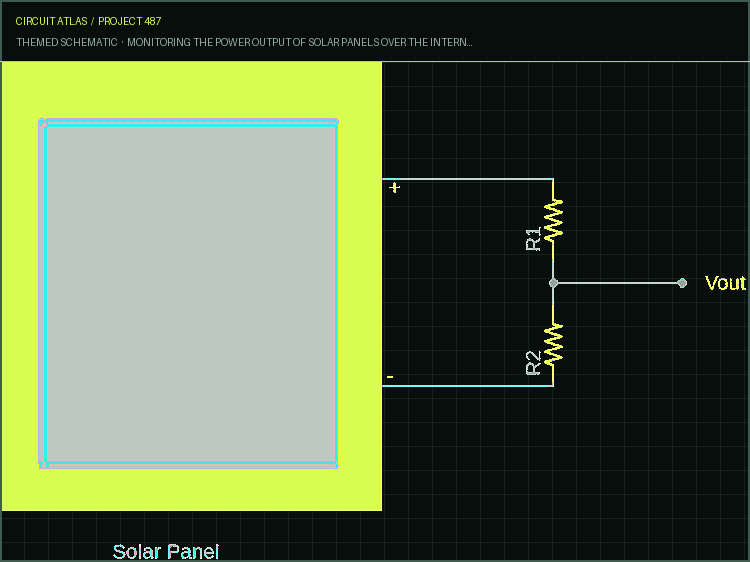
Project build noteThe measuring of the voltage produced by solar panels requires the utilization of a voltage divider. When selecting a voltage divider, one should look for one that can split the voltage in accordance with the microcontroller's I/O voltage input. You should select the aforementioned resistors in such a manner that the output voltage of the voltage divider does not exceed the maximum I/O voltage of the microcontroller (3.3V for ESP32). Potentiometers, on the
other hand, are recommended due to the versatility they allow in terms of selecting a solar panel with either a greater or lower voltage rating and the ease with which the voltage may be set with a multimeter. In our particular setup, the MPPT board circuit includes a potentiometer that performs the function of a voltage divider. We determined that a division factor of 6V would work best for the voltage divider. We connected two multimeters, one in the input and another in the output of the pot, and fixed the value so that the output would be 3V when the input voltage was 18V. This was done because the solar panel's nominal output voltage is 18V.
Monitoring Solar Panel Temperature
Project build noteThe temperature of a solar panel has a direct bearing on the amount of power that can be extracted from that panel. Why? Because as the temperature of a solar panel begins to rise, the amount of current that is produced by the panel climbs exponentially while the amount of voltage that is produced begins to decrease linearly.
According to the formula for power, which states that wattage is equal to voltage times current (W = V x A), a reduction in output voltage also results in a reduction in the solar panel's output power, and this occurs even when the flow of current is increased. The next issue that arises in our minds is, "How can we accurately estimate the temperature of the sun?" It is fairly intriguing to consider, considering that solar panels are typically subjected to a hot environment due to the fact that they are exposed to direct sunlight and for the obvious reasons. Utilizing a temperature sensor that is designed for flat surfaces is the most accurate method for measuring the temperature of solar panels. It is also recommended to utilize a thermocouple of the K type, which should be installed directly in the solar panel.
Circuit Diagram
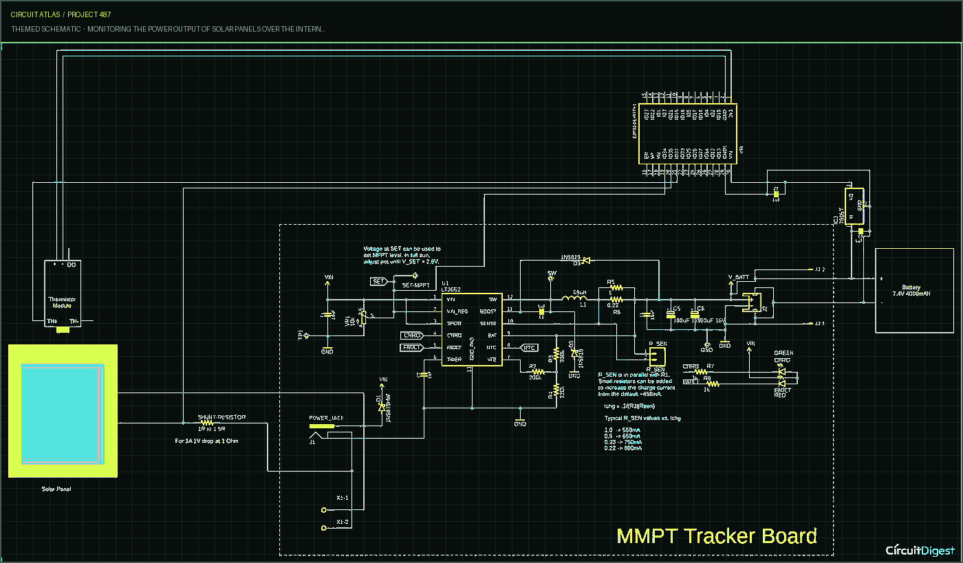
Project build noteThe following is an illustration of the whole circuit diagram for the Internet of Things-enabled solar power monitor. The diagram is easy to understand.
Our MPPT board, which is represented by the red board with dashes on it, may be seen in this particular project.
Setting up the ThingSpeak
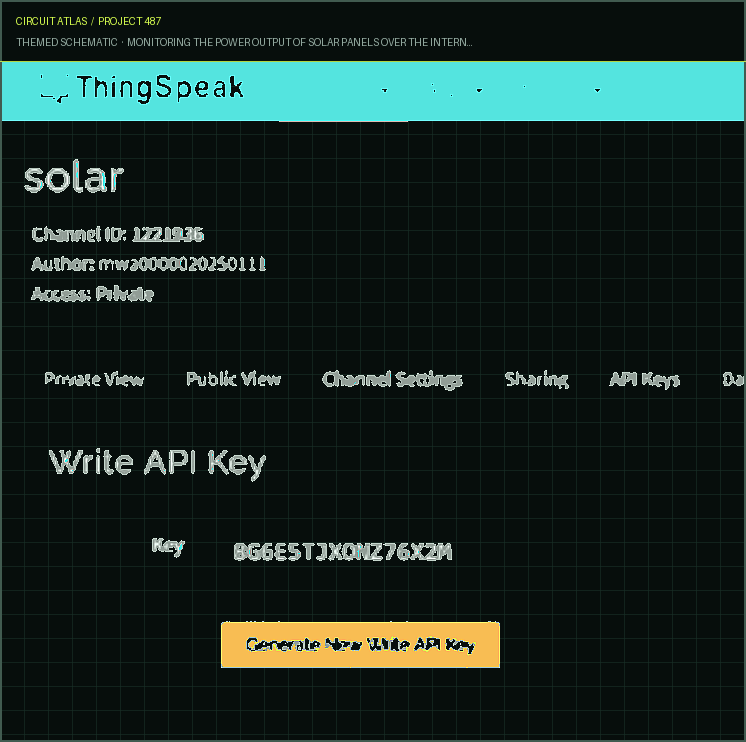
Project build noteAfter signing up for an account with ThingSpeak, navigate to the "my channel" section of the site, and then select the New Channel option. Make a new channel that contains the names of the fields. After you have completed creating the field, navigate to the API Keys field, where you will find the Write API Key. This key has to be provided in the code, and the channel ID has to be specified as well. Testing and Monitoring Data
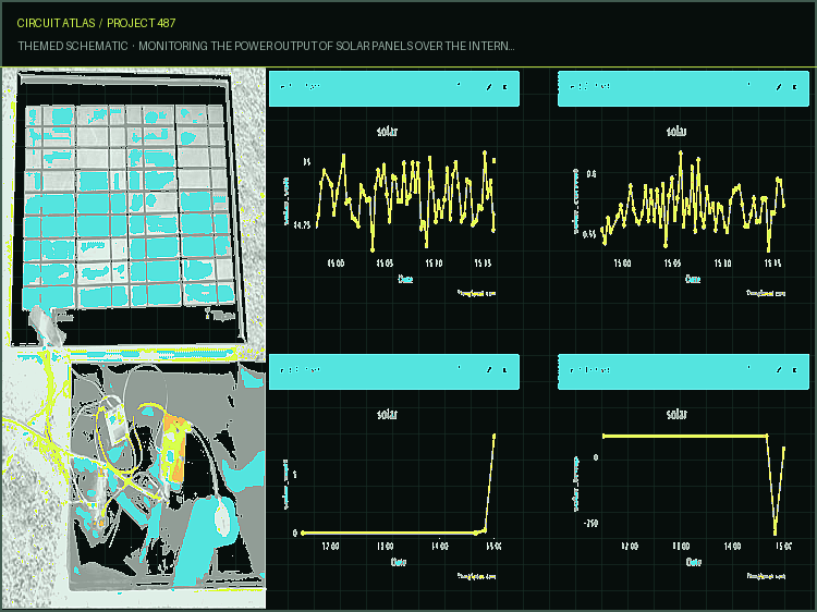
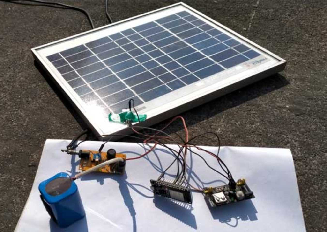
As can be seen in the following diagram, the testing procedure involves connecting the solar panel to the circuit and exposing it to sunlight. The data for 15-minute intervals are presented in the graph that we just looked at. Because this is an outdoor operating project, an appropriate PCB in addition to a box that completely surrounds it is required. The enclosure needs to be constructed in such a way that it prevents moisture from entering the circuit even when it rains. to make adjustments to this circuit or to have a conversation about other aspects of this project.
You built Monitoring the power output of solar panels over the Internet of Things using ESP32 and ThingSpeak.
You followed the full workflow from understanding the mission to testing the finished project. That is a real engineering achievement - well done.
Audio Player Built with ESP32 for DIY Projects
Ready to reuse what you learned in another project from the same track?
Start this project →