ESP32-CAM Face Recognition Door Lock System
489.ESP32-CAM Face Recognition Door Lock System Nowadays, everyone is extremely concerned about their personal security, whether it be the protection of their data or the security of thei…
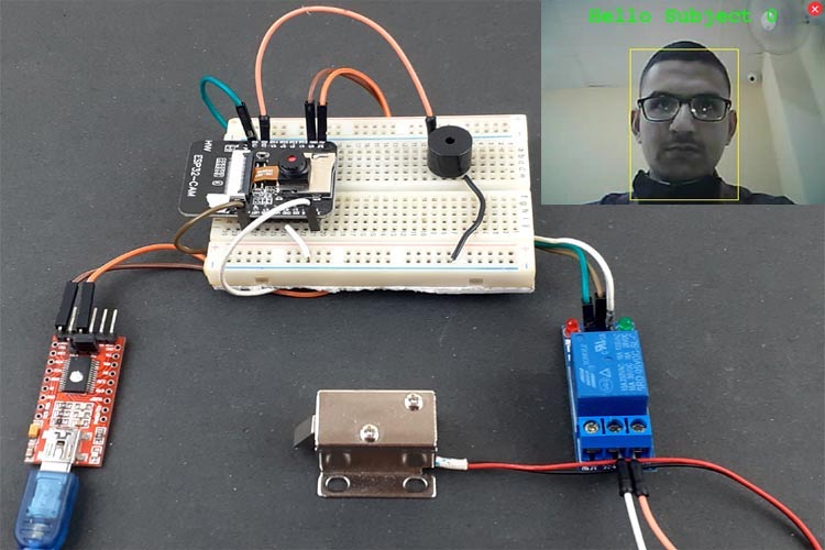
Know the mission before touching a wire.
Understand what you are making, prepare the right tools, and make the workbench safe.
Project details
ESP32-CAM Face Recognition Door Lock System is a iot project. 489.ESP32-CAM Face Recognition Door Lock System Nowadays, everyone is extremely concerned about their personal security, whether it be the protection of their data or the security of thei…
- Source pages
- 1382-1389
- Named parts
- 4
- Build goal
- Working, tested prototype
Tools you need
- Digital multimeter
- Wire stripper and side cutters
- Soldering iron with a fine tip
- Current-limited bench supply
- Computer with a data-capable USB cable
Use eye protection, good lighting, and a clean insulated surface throughout the build.
Safety precautions
- Disconnect every power source before changing a connection.
- Check component polarity, pinout, and supply voltage twice.
- Use a current limit for the first power-up.
- Keep liquids, loose metal, and uninsulated wires away from the bench.
Gather, identify, and understand every part.
Use the standardized inventory, then open What's this? to learn each part's role, advantages, limitations, handling, and specifications.
What's this?Image, role, pros, cons, handling & specifications
ESP32
A programmable controller that reads inputs, makes decisions, and drives the project's outputs.
What it does hereIt is the control centre and must use the documented board, pin map, supply, and logic level.
Buy / compare this part ↗Advantages
- Reprogrammable and reusable
- Large learning ecosystem
- Complex behaviour remains changeable
Limitations
- GPIO voltage and current are limited
- Some pins affect boot or communication
- Loads normally need a driver
Handling
- Disconnect power before rewiring
- Avoid static discharge
- Never power motors, relays, or pumps directly from GPIO
Specifications to verify
- Use the exact model, value, package, and rating listed for ESP32; similar-looking parts are not always interchangeable.
- Confirm operating voltage, logic level, pinout, memory, USB interface, and maximum GPIO current.
What's this?Image, role, pros, cons, handling & specifications
Relay module
An output component turns an electrical control signal into light, sound, motion, switching, or displayed information.
What it does hereIt presents the circuit result or acts on the physical world.
Buy / compare this part ↗Advantages
- Makes system state visible
- Can be tested separately
- Supports clear troubleshooting
Limitations
- Loads may exceed controller current
- Polarity or driver direction can matter
- Inductive loads create voltage spikes
Handling
- Use the documented driver stage
- Check polarity and load current
- Add flyback protection for inductive loads
Specifications to verify
- Use the exact model, value, package, and rating listed for Relay module; similar-looking parts are not always interchangeable.
- Confirm voltage, current, polarity, interface, driver requirements, and duty cycle.
What's this?Image, role, pros, cons, handling & specifications
Power supply
A power component supplies, converts, stores, or regulates energy for the project.
What it does hereIt must provide the documented voltage, polarity, isolation, and sufficient current safely.
Buy / compare this part ↗Advantages
- Stable power improves reliability
- Current limiting protects first tests
- Regulation reduces resets and noise
Limitations
- Wrong polarity can cause immediate damage
- Underrated parts overheat
- Mains circuits require qualified supervision
Handling
- Measure output before connection
- Use a fuse or current limit
- Insulate exposed conductors
Specifications to verify
- Use the exact model, value, package, and rating listed for Power supply; similar-looking parts are not always interchangeable.
- Confirm input/output voltage, current, polarity, connector, isolation, and thermal rating.
What's this?Image, role, pros, cons, handling & specifications
ESP32-CAM - controller board / IC
A programmable controller that reads inputs, makes decisions, and drives the project's outputs.
What it does hereIt is the control centre and must use the documented board, pin map, supply, and logic level.
Buy / compare this part ↗Advantages
- Reprogrammable and reusable
- Large learning ecosystem
- Complex behaviour remains changeable
Limitations
- GPIO voltage and current are limited
- Some pins affect boot or communication
- Loads normally need a driver
Handling
- Disconnect power before rewiring
- Avoid static discharge
- Never power motors, relays, or pumps directly from GPIO
Specifications to verify
- Use the exact model, value, package, and rating listed for ESP32-CAM - controller board / IC; similar-looking parts are not always interchangeable.
- Confirm operating voltage, logic level, pinout, memory, USB interface, and maximum GPIO current.
Connect one verified path at a time.
Explore the named components and standardized signal flow, then use Source Check to verify exact physical pins, values, and topology before applying power.
Trace this circuit.
ESP32-CAM Face Recognition Door Lock System: interactive parts, standardized terminals, responsive anchored wires, student explanations, and the original circuit reference in one shared system.
Trace before wiring
Follow power, ground, inputs, processing, and outputs in that order. Never guess a pin from package shape alone.
Connect with power off
Make short, labelled connections and share a common ground only where the schematic requires it.
Inspect every joint
Check continuity, polarity, adjacent shorts, and loose connections before the first power-up.
Open all source diagrams and build views 5 visuals
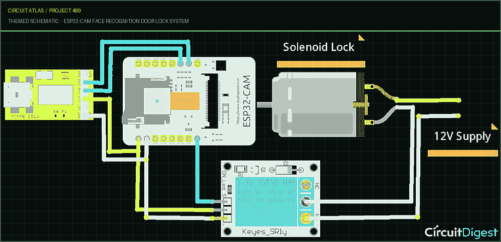
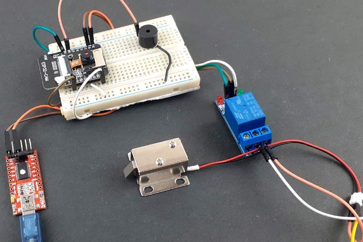
Confirm the hardware-only control path.
This project does not include firmware in the source. The circuit itself provides the required behaviour.
How to connect
- Match every controller label to the circuit view and source pin map.
- Join grounds before signal wires when separate low-voltage supplies are used.
- Keep motors, relays, pumps, and other loads on a suitable driver and external supply.
Common mistakes
Reversed VCC/GND, board-label versus GPIO-number confusion, missing common ground, and charge-only USB cables.
Troubleshoot
Disconnect loads, continuity-test one path at a time, then test with a current limit.
Software preparation
No IDE, board package, library, or firmware upload is required for this project.
If you add a programmable controller as an extension, document its pin map separately.
How to upload code
The original design is implemented entirely in hardware, so proceed after verifying the circuit and supply.
Assemble, deploy, test, and troubleshoot.
Use the complete source notes in build order, then pass the final checks before calling the project finished.
Build in functional stages
- Power and regulation
- Controller or processing stage
- Inputs and sensors
- Outputs and loads
- Enclosure and strain relief
Power up safely
- Inspect unpowered continuity first
- Apply the lowest safe current limit
- Measure supply rails before signals
- Add one load at a time
- Record expected and actual results
Work from simple to complex
- Confirm power, ground, polarity, and orientation
- Compare each pin with the source
- Test inputs separately from outputs
- Replace only one variable at a time
- Power off before every correction
Follow the documented instructions.
These notes come from this project's source and remain in their original order.
Project overview
Project build note489.ESP32-CAM Face Recognition Door Lock System Nowadays, everyone is extremely concerned about their personal security, whether it be the protection of their data or the security of their own home. These days, the use of digital door locks is extremely widespread due to the proliferation of connected devices and the general improvement of technology. The use of a physical key is not necessary to operate a digital
lock; rather, the lock can be controlled by means such as RFID, fingerprints, Face ID, pins, passwords, and so on. In the past, we have built a wide variety of applications using these various technologies, including digital door locks. Through the use of ESP32-CAM, we will construct a Face ID- controlled digital door lock system in this tutorial. The AI-Thinker ESP32-CAM module is an inexpensive development board that features a micro-SD card port in addition to a camera with a very compact form factor called an OV2640. It is equipped with a high- performance ESP32 S processor that includes built-in Wi-Fi and Bluetooth connectivity, as well as a 7-stage pipeline architecture and 2 high- performance 32-bit LX6 CPUs. In a previous article, we went over ESP32- CAM in depth and demonstrated how it might be used to construct a Wi-Fi door Video doorbell. This time around, we will make use of the ESP32- CAM to construct a Door Lock System that is based on Face Recognition by utilizing a Relay Module and a Solenoid Lock.
When a person approaches the door, the camera will take a picture of their face, check to see if it has been registered, and then either unlock the door or sound an alarm. If the face has not been registered, the camera will sound an alarm, take a picture, and send it to the number that has been registered. The operation of the system is exactly like this.
ESP32 CAM
Project build noteFTDI Board Relay Module Solenoid Lock Jumper Wires Solenoid Lock The electronic-mechanical locking mechanism is utilized in the operation of a solenoid lock. This particular style of lock has a slug that has a cut that is angled and an effective mounting bracket. DC produces a magnetic field when power is applied, which moves the slug inside and retains the door in the unlocked position. This field also prevents the door from being locked. The slug will continue to remain in its position till the power is turned off. After the electricity has been cut off, the slug will exit the building and shut the door behind it. When it is locked, it does not consume any power at all. In order to power the solenoid lock, you will need a power supply that can deliver 12 volts at a current of 500 milliamps.
Circuit Diagram
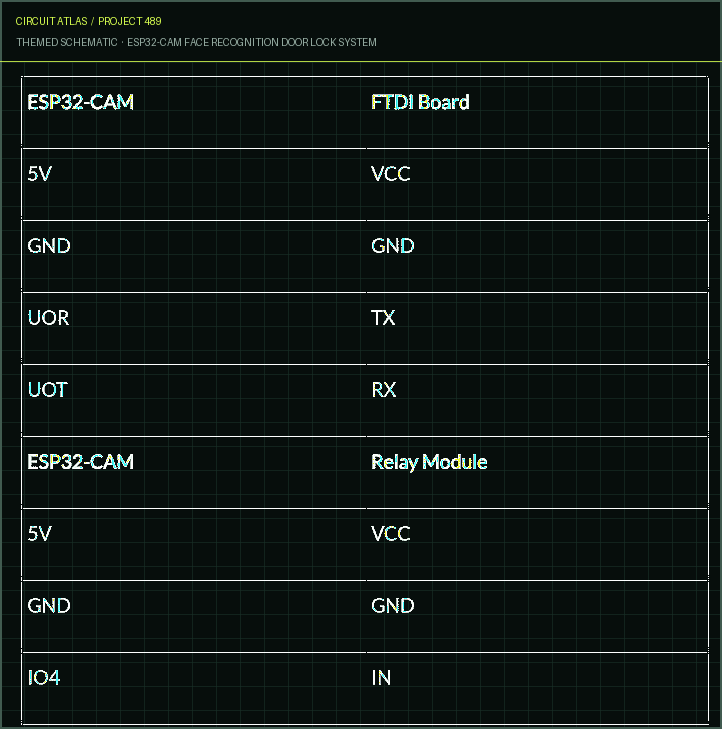
Project build noteCombination of the circuit described above with an FTDI board, a relay module, and a solenoid lock. Because the ESP32-CAM doesn't have a USB connector, the FTDI board is what's used to flash the code into it. Meanwhile, the relay module is what's utilized to turn the solenoid lock on and off. The VCC and GND pins of the FTDI board and the Relay module are linked to the ESP32-CAM's Vcc and GND pins. The ESP32's RX and TX ports are connected to the FTDI board's RX and TX ports, and the IN pin of the relay module is connected to the IO4 port on the ESP32-CAM.
Important: Before you upload the code, make sure that the IO0 is connected to the ground. IO0 is responsible for determining whether or not the ESP32 is operating in flashing mode. The ESP32 enters flashing mode when the GND pin on GPIO 0 is connected to ground. Code Explanation In the prior piece, we discussed how to use ESP32 for face recognition. In this piece, we will alter the code so that it can be used to control a solenoid door lock. The entire code may be broken down into four distinct sections. The first code is the primary one for the camera and relay module, which is where the ESP32 determines whether or not to lock or unlock the door based on face recognition. The other three codes are for the web page, camera index, and camera pins, respectively. The entirety of the code may
be found at the bottom of this page. In this section, we will go through some of the most significant aspects of the code. When all of the components have been connected in accordance with the
circuit design, it should look somewhat like this
Project build noteTesting the ESP32-CAM Face Recognition Door Lock System Last but not least, in order to upload the code, connect the FDTI board to your laptop and then pick the 'ESP32 Wrover Module' as the board you want to use. Alter the other settings as well, so that they match the picture
that follows
Project build noteBefore you click the button to upload the code, make sure the IO0 pin is connected to GND and then hit the reset button on the ESP32. After that, click the button labeled upload.
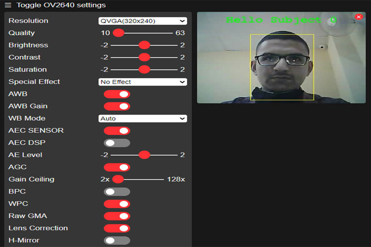
Note: If you are having trouble uploading the code and are getting errors, make sure that IO0 is connected to GND and that the appropriate parameters were selected in the Tools menu. After the code has been uploaded, the IO0 and GND pins should be removed. The serial monitor should then be opened, and the baud rate should be changed to 115200. After that, you will need to push the reset button on the ESP32, and the serial monitor will display the ESP's IP address as well as the port number. In order to access the camera streaming, you will now need to navigate to the browser and enter the ESP IP address that was copied from the Serial monitor. It will lead you to the page where you may stream the video. Simply select the "Start Stream" option located at the very bottom of the page to get the live video feed started. In order for the ESP32-CAM to be able to recognize the faces, we must first enroll the faces. To accomplish this, navigate to the settings menu and activate the Face recognition and detection functions. After that, click the Enroll Face button. There may be more than one opportunity to redeem oneself. After the face has been saved, the system recognizes it as subject 0, where 0 is the face number.
After enrolling the faces, the ESP32 will make the relay module high to unlock the door if it finds a face matching one of the enrolled faces in the video feed.
You built ESP32-CAM Face Recognition Door Lock System.
You followed the full workflow from understanding the mission to testing the finished project. That is a real engineering achievement - well done.
Automatic Hand Sanitizer Dispenser with COVID19
Ready to reuse what you learned in another project from the same track?
Start this project →