Manual EPROM Programmer
Most electrically programmable read-only memories (EPROMs) cost a lot to program because they need special devices called programmers. Here is a low-cost circuit for programming binary da…
Know the mission before touching a wire.
Understand what you are making, prepare the right tools, and make the workbench safe.
Project details
Manual EPROM Programmer is a electronics project. Most electrically programmable read-only memories (EPROMs) cost a lot to program because they need special devices called programmers. Here is a low-cost circuit for programming binary da…
- Source pages
- 505-508
- Named parts
- 4
- Build goal
- Working, tested prototype
Tools you need
- Digital multimeter
- Wire stripper and side cutters
- Soldering iron with a fine tip
- Current-limited bench supply
Use eye protection, good lighting, and a clean insulated surface throughout the build.
Safety precautions
- Disconnect every power source before changing a connection.
- Check component polarity, pinout, and supply voltage twice.
- Use a current limit for the first power-up.
- This project may involve hazardous voltage. Work only with qualified supervision and proper isolation.
Gather, identify, and understand every part.
Use the standardized inventory, then open What's this? to learn each part's role, advantages, limitations, handling, and specifications.
What's this?Image, role, pros, cons, handling & specifications
Power supply
A power component supplies, converts, stores, or regulates energy for the project.
What it does hereIt must provide the documented voltage, polarity, isolation, and sufficient current safely.
Buy / compare this part ↗Advantages
- Stable power improves reliability
- Current limiting protects first tests
- Regulation reduces resets and noise
Limitations
- Wrong polarity can cause immediate damage
- Underrated parts overheat
- Mains circuits require qualified supervision
Handling
- Measure output before connection
- Use a fuse or current limit
- Insulate exposed conductors
Specifications to verify
- Use the exact model, value, package, and rating listed for Power supply; similar-looking parts are not always interchangeable.
- Confirm input/output voltage, current, polarity, connector, isolation, and thermal rating.
What's this?Image, role, pros, cons, handling & specifications
Transformer
A power component supplies, converts, stores, or regulates energy for the project.
What it does hereIt must provide the documented voltage, polarity, isolation, and sufficient current safely.
Buy / compare this part ↗Advantages
- Stable power improves reliability
- Current limiting protects first tests
- Regulation reduces resets and noise
Limitations
- Wrong polarity can cause immediate damage
- Underrated parts overheat
- Mains circuits require qualified supervision
Handling
- Measure output before connection
- Use a fuse or current limit
- Insulate exposed conductors
Specifications to verify
- Use the exact model, value, package, and rating listed for Transformer; similar-looking parts are not always interchangeable.
- Confirm input/output voltage, current, polarity, connector, isolation, and thermal rating.
What's this?Image, role, pros, cons, handling & specifications
 SEMICONDUCTOR LEARNING VIEW
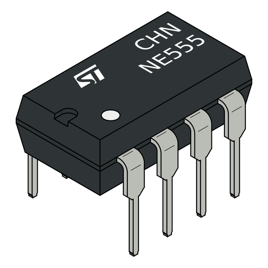
NE555
A semiconductor stage performs switching, amplification, regulation, rectification, or logic.
What it does hereIt controls current or signal flow at a defined point in the circuit.
Buy / compare this part ↗Advantages
- Fast and efficient
- Compact
- Can control larger loads from smaller signals
Limitations
- Pin order varies
- Sensitive to overvoltage and reverse polarity
- May need cooling or bias components
Handling
- Verify the datasheet pinout
- Avoid static and soldering heat
- Check notch, stripe, or flat-face orientation
Specifications to verify
- Use the exact model, value, package, and rating listed for NE555; similar-looking parts are not always interchangeable.
- Confirm pinout, maximum voltage/current, dissipation, gain or forward voltage, and package.
What's this?Image, role, pros, cons, handling & specifications
LED1 - indicator LED identified in the circuit
An output component turns an electrical control signal into light, sound, motion, switching, or displayed information.
What it does hereIt presents the circuit result or acts on the physical world.
Buy / compare this part ↗Advantages
- Makes system state visible
- Can be tested separately
- Supports clear troubleshooting
Limitations
- Loads may exceed controller current
- Polarity or driver direction can matter
- Inductive loads create voltage spikes
Handling
- Use the documented driver stage
- Check polarity and load current
- Add flyback protection for inductive loads
Specifications to verify
- Use the exact model, value, package, and rating listed for LED1 - indicator LED identified in the circuit; similar-looking parts are not always interchangeable.
- Confirm voltage, current, polarity, interface, driver requirements, and duty cycle.
Connect one verified path at a time.
Explore the named components and standardized signal flow, then use Source Check to verify exact physical pins, values, and topology before applying power.
Trace this circuit.
Manual EPROM Programmer: interactive parts, standardized terminals, responsive anchored wires, student explanations, and the original circuit reference in one shared system.
Trace before wiring
Follow power, ground, inputs, processing, and outputs in that order. Never guess a pin from package shape alone.
Connect with power off
Make short, labelled connections and share a common ground only where the schematic requires it.
Inspect every joint
Check continuity, polarity, adjacent shorts, and loose connections before the first power-up.
Open all source diagrams and build views 1 visuals
Confirm the hardware-only control path.
This project does not include firmware in the source. The circuit itself provides the required behaviour.
How to connect
- Match every controller label to the circuit view and source pin map.
- Join grounds before signal wires when separate low-voltage supplies are used.
- Keep motors, relays, pumps, and other loads on a suitable driver and external supply.
Common mistakes
Reversed VCC/GND, board-label versus GPIO-number confusion, missing common ground, and charge-only USB cables.
Troubleshoot
Disconnect loads, continuity-test one path at a time, then test with a current limit.
Software preparation
No IDE, board package, library, or firmware upload is required for this project.
If you add a programmable controller as an extension, document its pin map separately.
How to upload code
The original design is implemented entirely in hardware, so proceed after verifying the circuit and supply.
Assemble, deploy, test, and troubleshoot.
Use the complete source notes in build order, then pass the final checks before calling the project finished.
Build in functional stages
- Power and regulation
- Controller or processing stage
- Inputs and sensors
- Outputs and loads
- Enclosure and strain relief
Power up safely
- Inspect unpowered continuity first
- Apply the lowest safe current limit
- Measure supply rails before signals
- Add one load at a time
- Record expected and actual results
Work from simple to complex
- Confirm power, ground, polarity, and orientation
- Compare each pin with the source
- Test inputs separately from outputs
- Replace only one variable at a time
- Power off before every correction
Follow the documented instructions.
These notes come from this project's source and remain in their original order.
Project overview
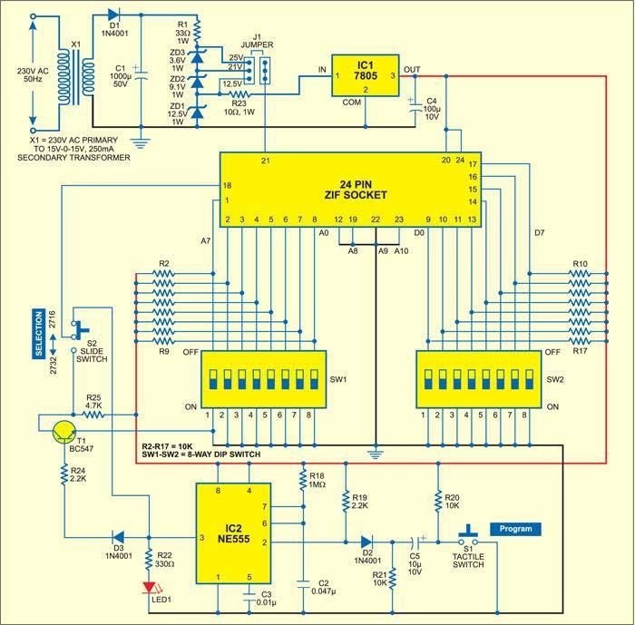
Project build noteMost electrically programmable read-only memories (EPROMs) cost a lot to program because they need special devices called programmers. Here is a low-cost circuit for programming binary data into EPROMs 2716 and 2732. EPROM Programmer Circuit The timer NE555 (IC2) is wired as a monostable for the circuit. When the push-to-on switch S1 is pressed, IC2 makes a 50ms pulse that is sent
through switch S2 to the program pin 18 of the ZIF SOCKET. For programming, the EPROM is put into the ZIF SOCKET. When the programming pulse is sent to the EPROM, LED1 lights up to let you know. Before sending the programming pulse to the EPROM, use jumper J1 to choose the programming voltage (25V, 21V, or 12.5V, depending on what the manufacturer says). This voltage will be sent to pin 21 of the ZIF SOCKET. The voltage that an EPROM needs to be programmed with is sometimes written on its body. The address and data for the EPROM (ZIF SOCKET) are set by the DIP switches SW1 and SW2, whose pins are initially pulled high by 10-kilo-ohm resistors.
The AC mains are stepped down by transformer X1 so that the secondary gives out 30V and 250 mA. The secondary output is blocked by capacitor C1 and turned back on by diode D1. With the help of zener diodes ZD1, ZD2, and ZD3, programming voltages of 25V, 21V, and 12.5V are made. IC1 is used to give the circuit a steady +5V supply.
Construction & testing
Project build noteFirst, read what's written on the EPROM about the programming voltage. Now, put the EPROM chip in the 24-pin ZIF socket and move the switch S2
as instructed by the EPROM. Then connect the power supply to give the circuit a steady 5V DC. Use jumper J1 to set the programming voltage, and use switches SW1 and SW2 to set the programming address and data value. After giving the necessary programming voltage, press the S1 switch to put the data at the address you want. Repeat this step for the next address and the data that goes with it.
You built Manual EPROM Programmer.
You followed the full workflow from understanding the mission to testing the finished project. That is a real engineering achievement - well done.
Noise Muting FM Receiver
Ready to reuse what you learned in another project from the same track?
Start this project →