Prepaid Energy Meter using GSM and Arduino
Electricity Energy Meters with prepaid balances are a solid idea because they allow you to refill them just like we do on our mobile phones. This project involves the use of Arduino and G…
Know the mission before touching a wire.
Understand what you are making, prepare the right tools, and make the workbench safe.
Project details
Prepaid Energy Meter using GSM and Arduino is a arduino project. Electricity Energy Meters with prepaid balances are a solid idea because they allow you to refill them just like we do on our mobile phones. This project involves the use of Arduino and G…
- Source pages
- 776-780
- Named parts
- 11
- Build goal
- Working, tested prototype
Tools you need
- Digital multimeter
- Wire stripper and side cutters
- Soldering iron with a fine tip
- Current-limited bench supply
- Computer with a data-capable USB cable
Use eye protection, good lighting, and a clean insulated surface throughout the build.
Safety precautions
- Disconnect every power source before changing a connection.
- Check component polarity, pinout, and supply voltage twice.
- Use a current limit for the first power-up.
- Keep liquids, loose metal, and uninsulated wires away from the bench.
Gather, identify, and understand every part.
Use the standardized inventory, then open What's this? to learn each part's role, advantages, limitations, handling, and specifications.
What's this?Image, role, pros, cons, handling & specifications
Arduino
A programmable controller that reads inputs, makes decisions, and drives the project's outputs.
What it does hereIt is the control centre and must use the documented board, pin map, supply, and logic level.
Buy / compare this part ↗Advantages
- Reprogrammable and reusable
- Large learning ecosystem
- Complex behaviour remains changeable
Limitations
- GPIO voltage and current are limited
- Some pins affect boot or communication
- Loads normally need a driver
Handling
- Disconnect power before rewiring
- Avoid static discharge
- Never power motors, relays, or pumps directly from GPIO
Specifications to verify
- Use the exact model, value, package, and rating listed for Arduino; similar-looking parts are not always interchangeable.
- Confirm operating voltage, logic level, pinout, memory, USB interface, and maximum GPIO current.
What's this?Image, role, pros, cons, handling & specifications
GSM Module
A named project component whose exact role is defined by the source circuit and build guide.
What it does hereIt performs a documented electrical, control, interface, or construction function in this project.
Buy / compare this part ↗Advantages
- Selected for this project
- Can be checked independently
- Supports modular troubleshooting
Limitations
- Substitutes may differ
- Generic names can hide variants
- Pinouts and ratings vary
Handling
- Compare the received part with the source
- Keep it labelled
- Do not force connectors or adjusters
Specifications to verify
- Use the exact model, value, package, and rating listed for GSM Module; similar-looking parts are not always interchangeable.
- Confirm dimensions, ratings, connection method, polarity, and environmental limits.
What's this?Image, role, pros, cons, handling & specifications
x2 LCD
An output component turns an electrical control signal into light, sound, motion, switching, or displayed information.
What it does hereIt presents the circuit result or acts on the physical world.
Buy / compare this part ↗Advantages
- Makes system state visible
- Can be tested separately
- Supports clear troubleshooting
Limitations
- Loads may exceed controller current
- Polarity or driver direction can matter
- Inductive loads create voltage spikes
Handling
- Use the documented driver stage
- Check polarity and load current
- Add flyback protection for inductive loads
Specifications to verify
- Use the exact model, value, package, and rating listed for x2 LCD; similar-looking parts are not always interchangeable.
- Confirm voltage, current, polarity, interface, driver requirements, and duty cycle.
What's this?Image, role, pros, cons, handling & specifications
Analogue Electricity Energy Meter
An output component turns an electrical control signal into light, sound, motion, switching, or displayed information.
What it does hereIt presents the circuit result or acts on the physical world.
Buy / compare this part ↗Advantages
- Makes system state visible
- Can be tested separately
- Supports clear troubleshooting
Limitations
- Loads may exceed controller current
- Polarity or driver direction can matter
- Inductive loads create voltage spikes
Handling
- Use the documented driver stage
- Check polarity and load current
- Add flyback protection for inductive loads
Specifications to verify
- Use the exact model, value, package, and rating listed for Analogue Electricity Energy Meter; similar-looking parts are not always interchangeable.
- Confirm voltage, current, polarity, interface, driver requirements, and duty cycle.
What's this?Image, role, pros, cons, handling & specifications
Optocoupler 4n35
A named project component whose exact role is defined by the source circuit and build guide.
What it does hereIt performs a documented electrical, control, interface, or construction function in this project.
Buy / compare this part ↗Advantages
- Selected for this project
- Can be checked independently
- Supports modular troubleshooting
Limitations
- Substitutes may differ
- Generic names can hide variants
- Pinouts and ratings vary
Handling
- Compare the received part with the source
- Keep it labelled
- Do not force connectors or adjusters
Specifications to verify
- Use the exact model, value, package, and rating listed for Optocoupler 4n35; similar-looking parts are not always interchangeable.
- Confirm dimensions, ratings, connection method, polarity, and environmental limits.
What's this?Image, role, pros, cons, handling & specifications
POT
A named project component whose exact role is defined by the source circuit and build guide.
What it does hereIt performs a documented electrical, control, interface, or construction function in this project.
Buy / compare this part ↗Advantages
- Selected for this project
- Can be checked independently
- Supports modular troubleshooting
Limitations
- Substitutes may differ
- Generic names can hide variants
- Pinouts and ratings vary
Handling
- Compare the received part with the source
- Keep it labelled
- Do not force connectors or adjusters
Specifications to verify
- Use the exact model, value, package, and rating listed for POT; similar-looking parts are not always interchangeable.
- Confirm dimensions, ratings, connection method, polarity, and environmental limits.
What's this?Image, role, pros, cons, handling & specifications
Bulb and holder
A named project component whose exact role is defined by the source circuit and build guide.
What it does hereIt performs a documented electrical, control, interface, or construction function in this project.
Buy / compare this part ↗Advantages
- Selected for this project
- Can be checked independently
- Supports modular troubleshooting
Limitations
- Substitutes may differ
- Generic names can hide variants
- Pinouts and ratings vary
Handling
- Compare the received part with the source
- Keep it labelled
- Do not force connectors or adjusters
Specifications to verify
- Use the exact model, value, package, and rating listed for Bulb and holder; similar-looking parts are not always interchangeable.
- Confirm dimensions, ratings, connection method, polarity, and environmental limits.
What's this?Image, role, pros, cons, handling & specifications
SIM card
A named project component whose exact role is defined by the source circuit and build guide.
What it does hereIt performs a documented electrical, control, interface, or construction function in this project.
Buy / compare this part ↗Advantages
- Selected for this project
- Can be checked independently
- Supports modular troubleshooting
Limitations
- Substitutes may differ
- Generic names can hide variants
- Pinouts and ratings vary
Handling
- Compare the received part with the source
- Keep it labelled
- Do not force connectors or adjusters
Specifications to verify
- Use the exact model, value, package, and rating listed for SIM card; similar-looking parts are not always interchangeable.
- Confirm dimensions, ratings, connection method, polarity, and environmental limits.
What's this?Image, role, pros, cons, handling & specifications
Power supply
A power component supplies, converts, stores, or regulates energy for the project.
What it does hereIt must provide the documented voltage, polarity, isolation, and sufficient current safely.
Buy / compare this part ↗Advantages
- Stable power improves reliability
- Current limiting protects first tests
- Regulation reduces resets and noise
Limitations
- Wrong polarity can cause immediate damage
- Underrated parts overheat
- Mains circuits require qualified supervision
Handling
- Measure output before connection
- Use a fuse or current limit
- Insulate exposed conductors
Specifications to verify
- Use the exact model, value, package, and rating listed for Power supply; similar-looking parts are not always interchangeable.
- Confirm input/output voltage, current, polarity, connector, isolation, and thermal rating.
What's this?Image, role, pros, cons, handling & specifications
Mobile Phone
A named project component whose exact role is defined by the source circuit and build guide.
What it does hereIt performs a documented electrical, control, interface, or construction function in this project.
Buy / compare this part ↗Advantages
- Selected for this project
- Can be checked independently
- Supports modular troubleshooting
Limitations
- Substitutes may differ
- Generic names can hide variants
- Pinouts and ratings vary
Handling
- Compare the received part with the source
- Keep it labelled
- Do not force connectors or adjusters
Specifications to verify
- Use the exact model, value, package, and rating listed for Mobile Phone; similar-looking parts are not always interchangeable.
- Confirm dimensions, ratings, connection method, polarity, and environmental limits.
What's this?Image, role, pros, cons, handling & specifications
ULN2003 - integrated circuit
A semiconductor stage performs switching, amplification, regulation, rectification, or logic.
What it does hereIt controls current or signal flow at a defined point in the circuit.
Buy / compare this part ↗Advantages
- Fast and efficient
- Compact
- Can control larger loads from smaller signals
Limitations
- Pin order varies
- Sensitive to overvoltage and reverse polarity
- May need cooling or bias components
Handling
- Verify the datasheet pinout
- Avoid static and soldering heat
- Check notch, stripe, or flat-face orientation
Specifications to verify
- Use the exact model, value, package, and rating listed for ULN2003 - integrated circuit; similar-looking parts are not always interchangeable.
- Confirm pinout, maximum voltage/current, dissipation, gain or forward voltage, and package.
Connect one verified path at a time.
Explore the named components and standardized signal flow, then use Source Check to verify exact physical pins, values, and topology before applying power.
Trace this circuit.
Prepaid Energy Meter using GSM and Arduino: interactive parts, standardized terminals, responsive anchored wires, student explanations, and the original circuit reference in one shared system.
Trace before wiring
Follow power, ground, inputs, processing, and outputs in that order. Never guess a pin from package shape alone.
Connect with power off
Make short, labelled connections and share a common ground only where the schematic requires it.
Inspect every joint
Check continuity, polarity, adjacent shorts, and loose connections before the first power-up.
Open all source diagrams and build views 3 visuals
Confirm the hardware-only control path.
This project does not include firmware in the source. The circuit itself provides the required behaviour.
How to connect
- Match every controller label to the circuit view and source pin map.
- Join grounds before signal wires when separate low-voltage supplies are used.
- Keep motors, relays, pumps, and other loads on a suitable driver and external supply.
Common mistakes
Reversed VCC/GND, board-label versus GPIO-number confusion, missing common ground, and charge-only USB cables.
Troubleshoot
Disconnect loads, continuity-test one path at a time, then test with a current limit.
Software preparation
No IDE, board package, library, or firmware upload is required for this project.
If you add a programmable controller as an extension, document its pin map separately.
How to upload code
The original design is implemented entirely in hardware, so proceed after verifying the circuit and supply.
Assemble, deploy, test, and troubleshoot.
Use the complete source notes in build order, then pass the final checks before calling the project finished.
Build in functional stages
- Power and regulation
- Controller or processing stage
- Inputs and sensors
- Outputs and loads
- Enclosure and strain relief
Power up safely
- Inspect unpowered continuity first
- Apply the lowest safe current limit
- Measure supply rails before signals
- Add one load at a time
- Record expected and actual results
Work from simple to complex
- Confirm power, ground, polarity, and orientation
- Compare each pin with the source
- Test inputs separately from outputs
- Replace only one variable at a time
- Power off before every correction
Follow the documented instructions.
These notes come from this project's source and remain in their original order.
Project overview
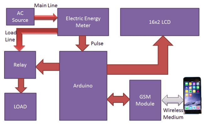
Project build noteElectricity Energy Meters with prepaid balances are a solid idea because they allow you to refill them just like we do on our mobile phones. This project involves the use of Arduino and GSM modules to create an automated system. This system allows electricity balances to be recharged through SMS messages. If the system is unbalanced or low, it can stop the power supply to the house. And this system will automatically send users updates on their mobile devices, such as low balance alerts, cut off alerts, resume alerts, and recharge alerts, depending on the energy meter readings.
Working explanation
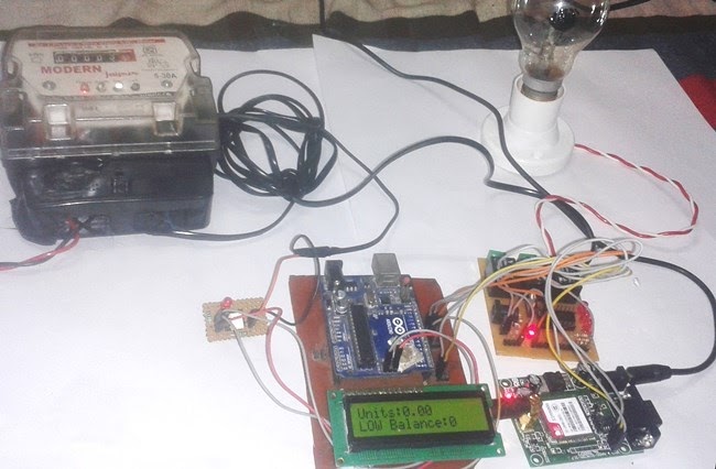
Project build noteUsing an Arduino and the power meter's calibration LED, we have interfaced the energy meter with Arduino. Our CAL LED only needs to be connected to an Arduino by means of an Optocoupler IC. Fig. Prototype of Energy Meter using GSM and Arduino
Components used
Project build noteArduino GSM Module 16x2 LCD Analogue Electricity Energy Meter Optocoupler 4n35 Resistors POT Connecting wires Bulb and holder SIM card Power supply Mobile Phone
As soon as the system comes on, it reads previous rupee values from EEPROM and restores them into variables; it compares the value with the predefined one and decides whether to proceed. Use relays to switch on the electricity of a house or office if the available amount is more than 15 rupees, for example. Once the balance falls below 15 rupees, Arduino sends a SMS to the phone of the user informing them of the low balance and asking them to recharge soon. The Arduino turns off the electricity supply of the home when the balance falls beneath 5 rupees and sends a SMS alerting the user of a 'Light Cut' and requesting him to recharge soon. Here you can find information on the GSM module and AT commands used to send and receive messages.
Now that our system can be recharged through our cell phones, we can do so simply by sending a SMS to it. We would send #45* if we want to recharge 45 dollars, here the # and * indicate the sum to be recharged. Upon receiving this message, the system extracts the recharge amount to update the system balance. In the video at the end, you will see how the system turns on the electricity in the house or office.
Circuit Description
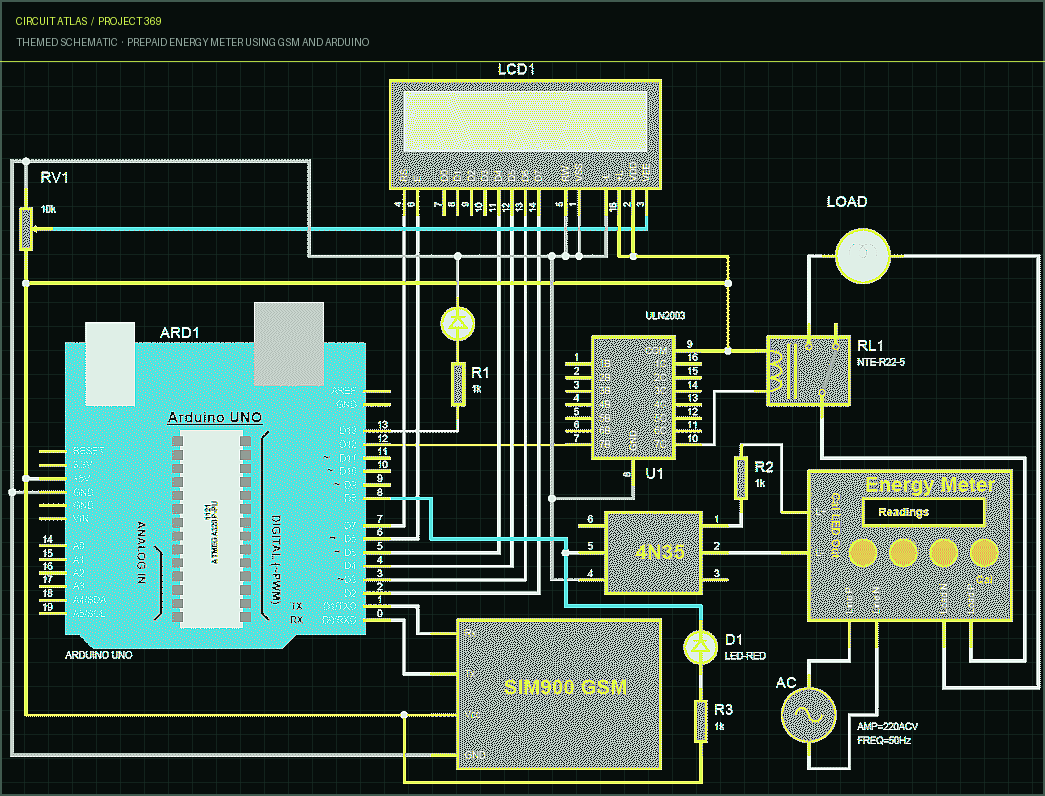
Project build noteA schematic of the project circuit connections is shown; an Arduino UNO processor has been used to process all the components. Unit status and remaining balance are displayed on a liquid crystal display. LCD pins RS, EN, D4, D5, D6, D7 are connected to Arduino digital pin number 7, 6, 5, 4, 3, 2. GSM pins Rx and Tx are directly connected to Arduino pins Rx and Tx respectively. An adapter powered by 12 volts is used to power a GSM module. On pin 12 of Arduino, a relay is used to switch electricity through the ULN2003 relay driver.
How to Connect Energy Meter with Arduino
Project build noteAn Analogue Electricity Energy Meter must first be purchased by the user. Once it has been opened, the user can locate the terminals of Pulse LEDs and Cal LEDs (cathode and anode). Once you have soldered two wires in each terminal, remove them from the meter and close it. Then tighten the screws. Now the LED's anode terminal must be connected to pin number 1
of the optocoupler. On an optocoupler, pin number two is connected to the cathode terminal, and pin number four should be directly connected to ground. In the pin number 5 of the optocoupler is an LED and Pull-up resistor. A similar terminal should be connected to Arduino pin 8 as well. The aim of this project is to gather information about the usage of energy by a specific consumer or user, using a wireless communications system (not requiring a visit to the consumer's home or office), and the system is called AMR (Automatic Meter Reading). AMR would involve remotely accumulating meter readings at a location through a wireless telecommunications system, instead of individuals visiting the site physically and taking notes.
You built Prepaid Energy Meter using GSM and Arduino.
You followed the full workflow from understanding the mission to testing the finished project. That is a real engineering achievement - well done.
Clap Switch using Arduino
Ready to reuse what you learned in another project from the same track?
Start this project →