Clap Switch using Arduino
Using ARDUINO UNO as a platform, we will prototype a Clapper circuit using the ADC concept. In order to detect sound and generate a response, we are going to use a MIC and Uno. Clap ON Cl…
Know the mission before touching a wire.
Understand what you are making, prepare the right tools, and make the workbench safe.
Project details
Clap Switch using Arduino is a arduino project. Using ARDUINO UNO as a platform, we will prototype a Clapper circuit using the ADC concept. In order to detect sound and generate a response, we are going to use a MIC and Uno. Clap ON Cl…
- Source pages
- 780-784
- Named parts
- 4
- Build goal
- Working, tested prototype
Tools you need
- Digital multimeter
- Wire stripper and side cutters
- Soldering iron with a fine tip
- Current-limited bench supply
- Computer with a data-capable USB cable
Use eye protection, good lighting, and a clean insulated surface throughout the build.
Safety precautions
- Disconnect every power source before changing a connection.
- Check component polarity, pinout, and supply voltage twice.
- Use a current limit for the first power-up.
- This project may involve hazardous voltage. Work only with qualified supervision and proper isolation.
Gather, identify, and understand every part.
Use the standardized inventory, then open What's this? to learn each part's role, advantages, limitations, handling, and specifications.
What's this?Image, role, pros, cons, handling & specifications
Arduino Uno
A programmable controller that reads inputs, makes decisions, and drives the project's outputs.
What it does hereIt is the control centre and must use the documented board, pin map, supply, and logic level.
Buy / compare this part ↗Advantages
- Reprogrammable and reusable
- Large learning ecosystem
- Complex behaviour remains changeable
Limitations
- GPIO voltage and current are limited
- Some pins affect boot or communication
- Loads normally need a driver
Handling
- Disconnect power before rewiring
- Avoid static discharge
- Never power motors, relays, or pumps directly from GPIO
Specifications to verify
- Use the exact model, value, package, and rating listed for Arduino Uno; similar-looking parts are not always interchangeable.
- Confirm operating voltage, logic level, pinout, memory, USB interface, and maximum GPIO current.
What's this?Image, role, pros, cons, handling & specifications
Power supply
A power component supplies, converts, stores, or regulates energy for the project.
What it does hereIt must provide the documented voltage, polarity, isolation, and sufficient current safely.
Buy / compare this part ↗Advantages
- Stable power improves reliability
- Current limiting protects first tests
- Regulation reduces resets and noise
Limitations
- Wrong polarity can cause immediate damage
- Underrated parts overheat
- Mains circuits require qualified supervision
Handling
- Measure output before connection
- Use a fuse or current limit
- Insulate exposed conductors
Specifications to verify
- Use the exact model, value, package, and rating listed for Power supply; similar-looking parts are not always interchangeable.
- Confirm input/output voltage, current, polarity, connector, isolation, and thermal rating.
What's this?Image, role, pros, cons, handling & specifications
NEGATIVE
A named project component whose exact role is defined by the source circuit and build guide.
What it does hereIt performs a documented electrical, control, interface, or construction function in this project.
Buy / compare this part ↗Advantages
- Selected for this project
- Can be checked independently
- Supports modular troubleshooting
Limitations
- Substitutes may differ
- Generic names can hide variants
- Pinouts and ratings vary
Handling
- Compare the received part with the source
- Keep it labelled
- Do not force connectors or adjusters
Specifications to verify
- Use the exact model, value, package, and rating listed for NEGATIVE; similar-looking parts are not always interchangeable.
- Confirm dimensions, ratings, connection method, polarity, and environmental limits.
What's this?Image, role, pros, cons, handling & specifications
2N3904
A semiconductor stage performs switching, amplification, regulation, rectification, or logic.
What it does hereIt controls current or signal flow at a defined point in the circuit.
Buy / compare this part ↗Advantages
- Fast and efficient
- Compact
- Can control larger loads from smaller signals
Limitations
- Pin order varies
- Sensitive to overvoltage and reverse polarity
- May need cooling or bias components
Handling
- Verify the datasheet pinout
- Avoid static and soldering heat
- Check notch, stripe, or flat-face orientation
Specifications to verify
- Use the exact model, value, package, and rating listed for 2N3904; similar-looking parts are not always interchangeable.
- Confirm pinout, maximum voltage/current, dissipation, gain or forward voltage, and package.
Connect one verified path at a time.
Explore the named components and standardized signal flow, then use Source Check to verify exact physical pins, values, and topology before applying power.
Trace this circuit.
Clap Switch using Arduino: interactive parts, standardized terminals, responsive anchored wires, student explanations, and the original circuit reference in one shared system.
Trace before wiring
Follow power, ground, inputs, processing, and outputs in that order. Never guess a pin from package shape alone.
Connect with power off
Make short, labelled connections and share a common ground only where the schematic requires it.
Inspect every joint
Check continuity, polarity, adjacent shorts, and loose connections before the first power-up.
Open all source diagrams and build views 2 visuals
Prepare, upload, and verify the program.
Follow the same software sequence every time: verify connections, prepare the toolchain, compile, and upload.
How to connect
- Match every controller label to the circuit view and source pin map.
- Join grounds before signal wires when separate low-voltage supplies are used.
- Keep motors, relays, pumps, and other loads on a suitable driver and external supply.
Common mistakes
Reversed VCC/GND, board-label versus GPIO-number confusion, missing common ground, and charge-only USB cables.
Troubleshoot
Disconnect loads, continuity-test one path at a time, then test with a current limit.
Software preparation
- Install the current Arduino IDE or the software named in the guide.
- Install the correct board package and required libraries.
- Select the exact board, processor, and serial port.
- Compile once before connecting external loads.
How to upload code
- Connect the board with a data-capable USB cable.
- Open the documented sketch and confirm configuration values.
- Compile, fix the first reported error, and upload.
- Test with external loads disconnected first.
Common mistakes
Wrong port, missing library, incorrect board selection, boot pins held in the wrong state, or a busy serial port.
4. Program Arduino to Toggle the LED on each Clap
When the MIC is working properly, we get normal signals, so we also get
normal values in the UNO. The MIC provides a peak upon clapping; thanks
to this, we have a peak digital value in the UNO, the LED can then be
programmed to toggle ON when the peak is present. Thus, the LED
illuminates with the first clap and stays on. Once the LED has been turned
off, it will remain off until the next clap. Thus, we have a clapper circuit.Assemble, deploy, test, and troubleshoot.
Use the complete source notes in build order, then pass the final checks before calling the project finished.
Build in functional stages
- Power and regulation
- Controller or processing stage
- Inputs and sensors
- Outputs and loads
- Enclosure and strain relief
Power up safely
- Inspect unpowered continuity first
- Apply the lowest safe current limit
- Measure supply rails before signals
- Add one load at a time
- Record expected and actual results
Work from simple to complex
- Confirm power, ground, polarity, and orientation
- Compare each pin with the source
- Test inputs separately from outputs
- Replace only one variable at a time
- Power off before every correction
Follow the documented instructions.
These notes come from this project's source and remain in their original order.
Project overview
Project build noteUsing ARDUINO UNO as a platform, we will prototype a Clapper circuit using the ADC concept. In order to detect sound and generate a response, we are going to use a MIC and Uno. Clap ON Clap OFF switches the device by using clapping sound, however it does not work in reverse. The 555 Timer IC was previously used to build the Clap ON Clap OFF switch and Clap ON Clap OFF switch. In case of clapping, there is a peak signal in the microphone that is much higher than normal. That signal is sent to the amplifier via a high-pass filter. ADC converts this high voltage signal into a number using an amplification circuit. In other words, the ADC reading for the UNO will peak at that time. The project is described in detail below. When the peak is detected, the LED on the board will be toggled. MIC is a transducer that detects sound, converting audio energy into electrical energy. Hence sound is represented as a changing voltage with this sensor. A device like this is used mostly for recording or detecting sounds. All mobile phones and laptops have this type of transducer. A typical MIC
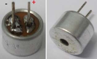
looks like this A typical MIC appears like, A typical MIC can be found in all mobile phones and laptops. A condenser mic's polarity can be determined in several ways. There are two terminals for MIC, one is positive, the other is negative. Using a multimeter, it is possible to check the polarity of the microphone. The positive probe of the Multimeter (the meter must be in DIODE TESTING mode) must be connected to the positive terminal of the MIC, and the negative probe must be connected to the negative terminal of the MIC. On the Multimeter, if the positive (MIC) terminal is at the negative terminal, it indicates the positive (MIC) terminal is at the negative terminal. The negative terminal has two or three soldering lines connected to the metal case. The positive terminal is similar, with one soldering line connected to the metal case. You can also check whether the connection between its metal case and the negative terminal is intact using continuity tester, in order to discover the negative terminal.
Hardware
Project build noteARDUINO UNO, power supply (5v), a condenser mic (explained above) 2N3904 NPN transistor, 100nF capacitors (2 pieces), one 100uF capacitor,
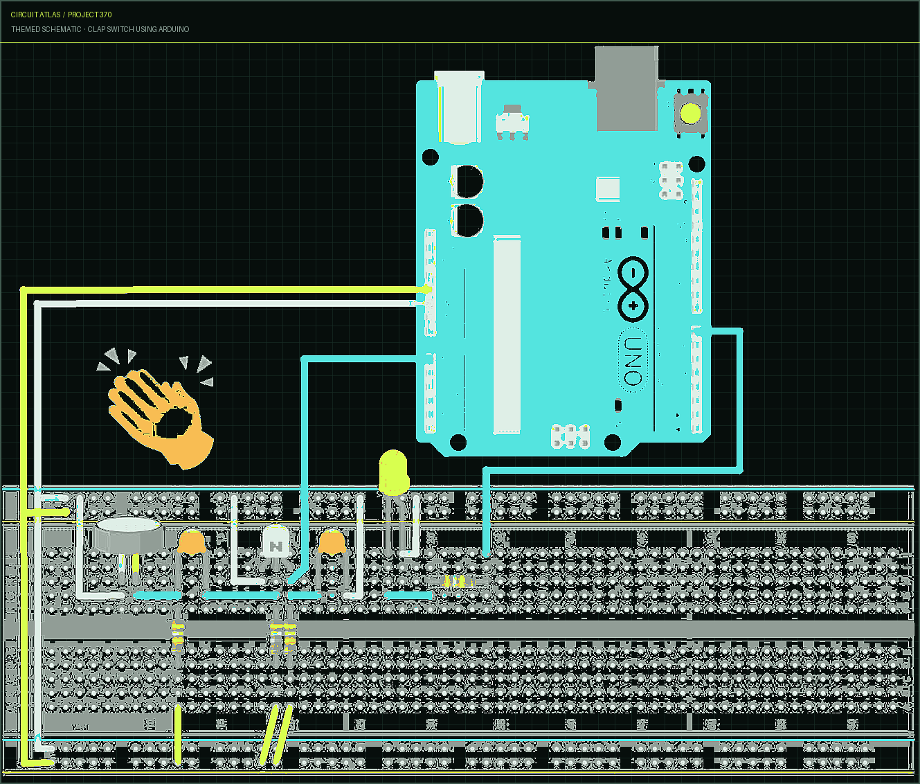
1K Ω resistor, 1MΩ resistor, 15KΩ resistor (2 pieces), one LED, And Breadboard & Connecting wires. Software: Arduino IDE In this figure, you can see the circuit diagram for the clapper project . There are four main parts to the process, namely: Filtration, Amplification, Analog-Digital conversion, and programming to control the LED.
Circuit Diagram and Working Explanation
Project build noteWhen sound is detected, the microphone can convert it into voltage that is proportional to the level of sound. We would assign a higher value to a higher sound, and a lower value to a lower sound.
In order to filter this signal, it is first fed into a High Pass Filter. This filtered value is then fed into the transistor to produce an amplified output, which is delivered through the collector. ADC0 of the UNO receives this collector signal, which is then converted to a digital signal. The LED is programmed to turn on with every increment of ADC channel A0, coupled into PIN 7 of PORTD.
1. Filtration
Project build noteIn the first instance, we will talk briefly about R-C High Pass Filters, which have been used to filter out noise. There is a single resistor and a single capacitor in this simple device. Keeping the circuit simple is all we need for this circuit, so we won't get bogged down in the details. Unlike low pass filters, high pass filters allow high frequency signals to pass through their input to output. In other words, input signals appear at the filter output if their frequency exceeds the filter's prescribed frequency. For now, we are not designing an audio amplifier, so we do not need to worry about these values. Here is the circuit for a high pass filter. A transistor then amplifies the voltage signal after passing through the filter.
2. Amplification
Project build noteIn order to drive the voltage of MIC, we need a transistor amplifier. Since the voltage of MIC is too low, it cannot be fed to the UNO for ADC (Analog to Digital Conversion). The voltages of MICs are amplified here with a single transistor amplifier. ADC0 of the Arduino receives the amplified voltage signal.
3. Analog to Digital Conversion
Project build noteThere are six analogs to digital converter channels on the ARDUINO. You can use any or all of them as analog voltage inputs. This means that input voltages within the range of 0-5 volts are translated into integer values within the range of 0-1023 using the UNO ADC of 10 bits. So, for every (5/1024= 4.9mV) per unit. We need to use the ADC channel of ARDUINO UNO in order to transform analog signals into digital signals, such as the
following
Project build noteReference values for ADC channels on the Arduino UNO are set to 5V. Therefore, we can provide feedback voltages of up to 5V on any input channel for ADC conversion. We have an instruction that enables us to change the reference value, as some sensors provide voltages of 0-2.5V, so with a 5V reference, the accuracy is reduced. The analog reference value can be changed using the "analogReference()" method. The ADC channel 0 reading can be performed by directly calling the function "analogRead(pin);", where "pin" represents the pin to which the analog signal was connected in our circuit, for instance "A0". By adding this instruction to the digital readout instruction "int sensorValue = analogRead(A0);", the value from the ADC is taken and converted into an integer for storage in the memory of the UNO.
You built Clap Switch using Arduino.
You followed the full workflow from understanding the mission to testing the finished project. That is a real engineering achievement - well done.
Bluetooth Controlled Toy Car using Arduino
Ready to reuse what you learned in another project from the same track?
Start this project →