LED Based Reading Lamp
This LED-based reading lamp circuit utilizes ultra-bright white LEDs to supply adequate light for reading while only consuming about 3 watts of power overall. In the event that there is a…
Know the mission before touching a wire.
Understand what you are making, prepare the right tools, and make the workbench safe.
Project details
LED Based Reading Lamp is a electronics project. This LED-based reading lamp circuit utilizes ultra-bright white LEDs to supply adequate light for reading while only consuming about 3 watts of power overall. In the event that there is a…
- Source pages
- 97-99
- Named parts
- 5
- Build goal
- Working, tested prototype
Tools you need
- Digital multimeter
- Wire stripper and side cutters
- Soldering iron with a fine tip
- Current-limited bench supply
Use eye protection, good lighting, and a clean insulated surface throughout the build.
Safety precautions
- Disconnect every power source before changing a connection.
- Check component polarity, pinout, and supply voltage twice.
- Use a current limit for the first power-up.
- This project may involve hazardous voltage. Work only with qualified supervision and proper isolation.
Gather, identify, and understand every part.
Use the standardized inventory, then open What's this? to learn each part's role, advantages, limitations, handling, and specifications.
What's this?Image, role, pros, cons, handling & specifications
Power supply
A power component supplies, converts, stores, or regulates energy for the project.
What it does hereIt must provide the documented voltage, polarity, isolation, and sufficient current safely.
Buy / compare this part ↗Advantages
- Stable power improves reliability
- Current limiting protects first tests
- Regulation reduces resets and noise
Limitations
- Wrong polarity can cause immediate damage
- Underrated parts overheat
- Mains circuits require qualified supervision
Handling
- Measure output before connection
- Use a fuse or current limit
- Insulate exposed conductors
Specifications to verify
- Use the exact model, value, package, and rating listed for Power supply; similar-looking parts are not always interchangeable.
- Confirm input/output voltage, current, polarity, connector, isolation, and thermal rating.
What's this?Image, role, pros, cons, handling & specifications
Transformer
A power component supplies, converts, stores, or regulates energy for the project.
What it does hereIt must provide the documented voltage, polarity, isolation, and sufficient current safely.
Buy / compare this part ↗Advantages
- Stable power improves reliability
- Current limiting protects first tests
- Regulation reduces resets and noise
Limitations
- Wrong polarity can cause immediate damage
- Underrated parts overheat
- Mains circuits require qualified supervision
Handling
- Measure output before connection
- Use a fuse or current limit
- Insulate exposed conductors
Specifications to verify
- Use the exact model, value, package, and rating listed for Transformer; similar-looking parts are not always interchangeable.
- Confirm input/output voltage, current, polarity, connector, isolation, and thermal rating.
What's this?Image, role, pros, cons, handling & specifications
MAXIMUM
A named project component whose exact role is defined by the source circuit and build guide.
What it does hereIt performs a documented electrical, control, interface, or construction function in this project.
Buy / compare this part ↗Advantages
- Selected for this project
- Can be checked independently
- Supports modular troubleshooting
Limitations
- Substitutes may differ
- Generic names can hide variants
- Pinouts and ratings vary
Handling
- Compare the received part with the source
- Keep it labelled
- Do not force connectors or adjusters
Specifications to verify
- Use the exact model, value, package, and rating listed for MAXIMUM; similar-looking parts are not always interchangeable.
- Confirm dimensions, ratings, connection method, polarity, and environmental limits.
What's this?Image, role, pros, cons, handling & specifications
 POWER LEARNING VIEW
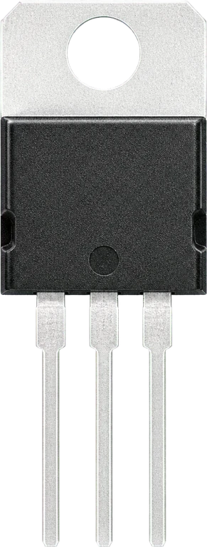
7805 - integrated circuit
A power component supplies, converts, stores, or regulates energy for the project.
What it does hereIt must provide the documented voltage, polarity, isolation, and sufficient current safely.
Buy / compare this part ↗Advantages
- Stable power improves reliability
- Current limiting protects first tests
- Regulation reduces resets and noise
Limitations
- Wrong polarity can cause immediate damage
- Underrated parts overheat
- Mains circuits require qualified supervision
Handling
- Measure output before connection
- Use a fuse or current limit
- Insulate exposed conductors
Specifications to verify
- Use the exact model, value, package, and rating listed for 7805 - integrated circuit; similar-looking parts are not always interchangeable.
- Confirm input/output voltage, current, polarity, connector, isolation, and thermal rating.
What's this?Image, role, pros, cons, handling & specifications
LED1, LED10 - indicator LEDs identified in the circuit
A named project component whose exact role is defined by the source circuit and build guide.
What it does hereIt performs a documented electrical, control, interface, or construction function in this project.
Buy / compare this part ↗Advantages
- Selected for this project
- Can be checked independently
- Supports modular troubleshooting
Limitations
- Substitutes may differ
- Generic names can hide variants
- Pinouts and ratings vary
Handling
- Compare the received part with the source
- Keep it labelled
- Do not force connectors or adjusters
Specifications to verify
- Use the exact model, value, package, and rating listed for LED1, LED10 - indicator LEDs identified in the circuit; similar-looking parts are not always interchangeable.
- Confirm dimensions, ratings, connection method, polarity, and environmental limits.
Connect one verified path at a time.
Explore the named components and standardized signal flow, then use Source Check to verify exact physical pins, values, and topology before applying power.
Trace this circuit.
LED Based Reading Lamp: interactive parts, standardized terminals, responsive anchored wires, student explanations, and the original circuit reference in one shared system.
Trace before wiring
Follow power, ground, inputs, processing, and outputs in that order. Never guess a pin from package shape alone.
Connect with power off
Make short, labelled connections and share a common ground only where the schematic requires it.
Inspect every joint
Check continuity, polarity, adjacent shorts, and loose connections before the first power-up.
Open all source diagrams and build views 1 visuals
Confirm the hardware-only control path.
This project does not include firmware in the source. The circuit itself provides the required behaviour.
How to connect
- Match every controller label to the circuit view and source pin map.
- Join grounds before signal wires when separate low-voltage supplies are used.
- Keep motors, relays, pumps, and other loads on a suitable driver and external supply.
Common mistakes
Reversed VCC/GND, board-label versus GPIO-number confusion, missing common ground, and charge-only USB cables.
Troubleshoot
Disconnect loads, continuity-test one path at a time, then test with a current limit.
Software preparation
No IDE, board package, library, or firmware upload is required for this project.
If you add a programmable controller as an extension, document its pin map separately.
How to upload code
The original design is implemented entirely in hardware, so proceed after verifying the circuit and supply.
Assemble, deploy, test, and troubleshoot.
Use the complete source notes in build order, then pass the final checks before calling the project finished.
Build in functional stages
- Power and regulation
- Controller or processing stage
- Inputs and sensors
- Outputs and loads
- Enclosure and strain relief
Power up safely
- Inspect unpowered continuity first
- Apply the lowest safe current limit
- Measure supply rails before signals
- Add one load at a time
- Record expected and actual results
Work from simple to complex
- Confirm power, ground, polarity, and orientation
- Compare each pin with the source
- Test inputs separately from outputs
- Replace only one variable at a time
- Power off before every correction
Follow the documented instructions.
These notes come from this project's source and remain in their original order.
Project overview
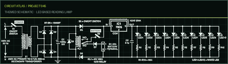
Project build noteThis LED-based reading lamp circuit utilizes ultra-bright white LEDs to supply adequate light for reading while only consuming about 3 watts of power overall. In the event that there is a problem with the AC mains, the battery backup circuit will immediately turn the LEDs on. When the power is restored, the lamp circuit will immediately switch back to operating off of AC mains, after which the battery supply will be automatically terminated. LED based reading lamp
The power supply circuit is made up of a step-down transformer with 0-7.5V and 500mA current capacity called X1, rectifier diodes numbered 1 through 4, and a filter capacitor called C1. Regulator IC 7805 (IC1) supplies regulated 5V to LEDs, ensuring that there is no variation in the intensity of the lamp light even if the mains power supply is unstable. This is accomplished by ensuring that LEDs are able to operate at a constant voltage. In total, ten white LEDs are linked in parallel across the 5V power supply. These LEDs are numbered from LED1 to LED10. To control the amount of current flowing through the white LEDs, resistors R1 through R10, each with a value of 56 ohms, are connected in series with the lights. It is possible to increase the brightness of the lamp light by adding additional LEDs in the same fashion; however, the lamp can only accommodate a maximum of 15 LEDs. When the power switch S1 is turned off, the relay RL1 becomes energized, and if the battery switch S2 is turned off, it will disconnect the 6V, 4Ah battery from the input to the regulator IC1. The battery is connected across the N/C contact of the relay RL1. When the power switch S1 is in the open position, relay RL1 is de-energized, and its N/C contacts connect the battery to the input of IC1 in the appropriate manner. Diodes D5 and D6 are reverse-current protection diodes, and their job is to prevent current from flowing from the battery towards the power supply section. Diode D7 is there to protect the battery from being discharged in the wrong direction. Check that the battery has been fully charged before you attempt to connect it.
Construction & Testing
Project build noteThe circuit can be put together on a PCB that is intended for general use. Place all ten white LEDs (LED1 through LED10) on the printed circuit board (PCB). Now take the bulb holder off of the lamp and adjust the PCB (the place where the bulb holder was mounted) so that the LED light illuminates your book in the correct manner. Because LEDs already have their own lens reflectors built in, separate reflectors are not
necessary to be used with them. It is recommended that you use a heat sink for IC1, as shown in the diagram. Caution: Even though you won't have any eye strain even after hours of reading in the light of this lamp, you shouldn't stare straight at white LEDs for an extended period of time.
You built LED Based Reading Lamp.
You followed the full workflow from understanding the mission to testing the finished project. That is a real engineering achievement - well done.
Multidoor Opening Alarm with Indicator
Ready to reuse what you learned in another project from the same track?
Start this project →