IoT Smart Agriculture & Automatic Irrigation System with ESP8266
ESP8266 We will learn about the IoT-based smart agriculture and automatic irrigation system with Nodemcu ESP8266 in this project. Agriculture is a key part of how agricultural countries g…
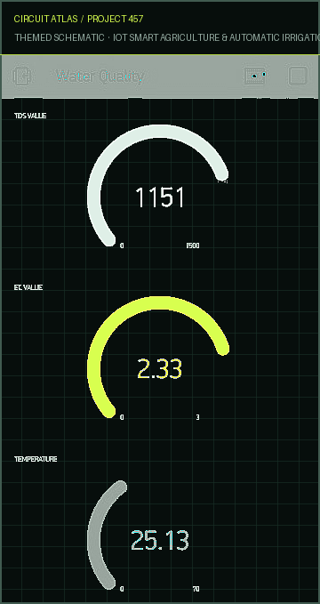
Know the mission before touching a wire.
Understand what you are making, prepare the right tools, and make the workbench safe.
Project details
IoT Smart Agriculture & Automatic Irrigation System with ESP8266 is a iot project. ESP8266 We will learn about the IoT-based smart agriculture and automatic irrigation system with Nodemcu ESP8266 in this project. Agriculture is a key part of how agricultural countries g…
- Source pages
- 1180-1185
- Named parts
- 6
- Build goal
- Working, tested prototype
Tools you need
- Digital multimeter
- Wire stripper and side cutters
- Soldering iron with a fine tip
- Current-limited bench supply
- Computer with a data-capable USB cable
Use eye protection, good lighting, and a clean insulated surface throughout the build.
Safety precautions
- Disconnect every power source before changing a connection.
- Check component polarity, pinout, and supply voltage twice.
- Use a current limit for the first power-up.
- Keep liquids, loose metal, and uninsulated wires away from the bench.
Gather, identify, and understand every part.
Use the standardized inventory, then open What's this? to learn each part's role, advantages, limitations, handling, and specifications.
What's this?Image, role, pros, cons, handling & specifications
 MODULE LEARNING VIEW
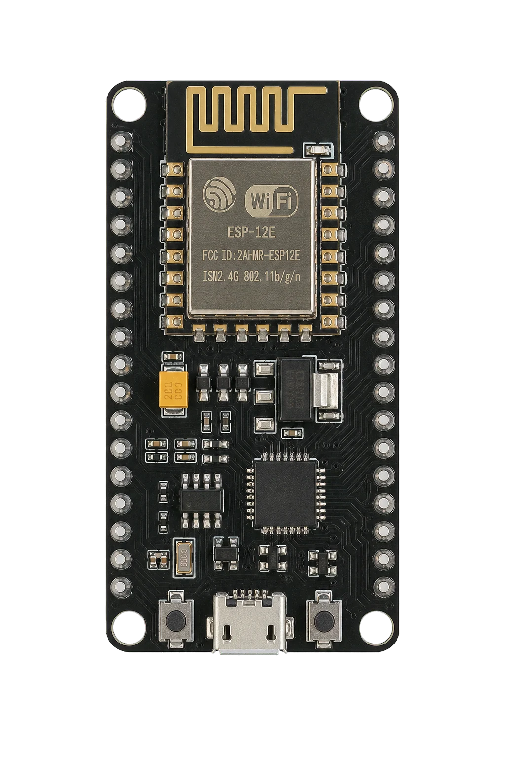
NodeMCU ESP8266
A programmable controller that reads inputs, makes decisions, and drives the project's outputs.
What it does hereIt is the control centre and must use the documented board, pin map, supply, and logic level.
Buy / compare this part ↗Advantages
- Reprogrammable and reusable
- Large learning ecosystem
- Complex behaviour remains changeable
Limitations
- GPIO voltage and current are limited
- Some pins affect boot or communication
- Loads normally need a driver
Handling
- Disconnect power before rewiring
- Avoid static discharge
- Never power motors, relays, or pumps directly from GPIO
Specifications to verify
- Use the exact model, value, package, and rating listed for NodeMCU ESP8266; similar-looking parts are not always interchangeable.
- Confirm operating voltage, logic level, pinout, memory, USB interface, and maximum GPIO current.
What's this?Image, role, pros, cons, handling & specifications
Soil Moisture Sensor
A sensor converts a physical condition into an electrical signal the circuit can measure.
What it does hereIt provides project input as an analogue, digital, resistive, frequency, or calibrated signal.
Buy / compare this part ↗Advantages
- Adds real-world awareness
- Can usually be tested independently
- Often supports calibration
Limitations
- Readings can drift
- Placement affects results
- Some sensors need warm-up or calibration
Handling
- Protect the sensing surface
- Observe supply voltage and polarity
- Keep signal leads away from noisy power wiring
Specifications to verify
- Use the exact model, value, package, and rating listed for Soil Moisture Sensor; similar-looking parts are not always interchangeable.
- Confirm supply range, output type, measurement range, accuracy, response time, and pin order.
What's this?Image, role, pros, cons, handling & specifications
OLED Display
An output component turns an electrical control signal into light, sound, motion, switching, or displayed information.
What it does hereIt presents the circuit result or acts on the physical world.
Buy / compare this part ↗Advantages
- Makes system state visible
- Can be tested separately
- Supports clear troubleshooting
Limitations
- Loads may exceed controller current
- Polarity or driver direction can matter
- Inductive loads create voltage spikes
Handling
- Use the documented driver stage
- Check polarity and load current
- Add flyback protection for inductive loads
Specifications to verify
- Use the exact model, value, package, and rating listed for OLED Display; similar-looking parts are not always interchangeable.
- Confirm voltage, current, polarity, interface, driver requirements, and duty cycle.
What's this?Image, role, pros, cons, handling & specifications
DHT11 Sensor
A sensor converts a physical condition into an electrical signal the circuit can measure.
What it does hereIt provides project input as an analogue, digital, resistive, frequency, or calibrated signal.
Buy / compare this part ↗Advantages
- Adds real-world awareness
- Can usually be tested independently
- Often supports calibration
Limitations
- Readings can drift
- Placement affects results
- Some sensors need warm-up or calibration
Handling
- Protect the sensing surface
- Observe supply voltage and polarity
- Keep signal leads away from noisy power wiring
Specifications to verify
- Use the exact model, value, package, and rating listed for DHT11 Sensor; similar-looking parts are not always interchangeable.
- Confirm supply range, output type, measurement range, accuracy, response time, and pin order.
What's this?Image, role, pros, cons, handling & specifications
Relay Module 5V
An output component turns an electrical control signal into light, sound, motion, switching, or displayed information.
What it does hereIt presents the circuit result or acts on the physical world.
Buy / compare this part ↗Advantages
- Makes system state visible
- Can be tested separately
- Supports clear troubleshooting
Limitations
- Loads may exceed controller current
- Polarity or driver direction can matter
- Inductive loads create voltage spikes
Handling
- Use the documented driver stage
- Check polarity and load current
- Add flyback protection for inductive loads
Specifications to verify
- Use the exact model, value, package, and rating listed for Relay Module 5V; similar-looking parts are not always interchangeable.
- Confirm voltage, current, polarity, interface, driver requirements, and duty cycle.
What's this?Image, role, pros, cons, handling & specifications
DC Motor Pump 5V
An output component turns an electrical control signal into light, sound, motion, switching, or displayed information.
What it does hereIt presents the circuit result or acts on the physical world.
Buy / compare this part ↗Advantages
- Makes system state visible
- Can be tested separately
- Supports clear troubleshooting
Limitations
- Loads may exceed controller current
- Polarity or driver direction can matter
- Inductive loads create voltage spikes
Handling
- Use the documented driver stage
- Check polarity and load current
- Add flyback protection for inductive loads
Specifications to verify
- Use the exact model, value, package, and rating listed for DC Motor Pump 5V; similar-looking parts are not always interchangeable.
- Confirm voltage, current, polarity, interface, driver requirements, and duty cycle.
Connect one verified path at a time.
Explore the named components and standardized signal flow, then use Source Check to verify exact physical pins, values, and topology before applying power.
Trace this circuit.
IoT Smart Agriculture & Automatic Irrigation System with ESP8266: interactive parts, standardized terminals, responsive anchored wires, student explanations, and the original circuit reference in one shared system.
Trace before wiring
Follow power, ground, inputs, processing, and outputs in that order. Never guess a pin from package shape alone.
Connect with power off
Make short, labelled connections and share a common ground only where the schematic requires it.
Inspect every joint
Check continuity, polarity, adjacent shorts, and loose connections before the first power-up.
Open all source diagrams and build views 5 visuals
Confirm the hardware-only control path.
This project does not include firmware in the source. The circuit itself provides the required behaviour.
How to connect
- Match every controller label to the circuit view and source pin map.
- Join grounds before signal wires when separate low-voltage supplies are used.
- Keep motors, relays, pumps, and other loads on a suitable driver and external supply.
Common mistakes
Reversed VCC/GND, board-label versus GPIO-number confusion, missing common ground, and charge-only USB cables.
Troubleshoot
Disconnect loads, continuity-test one path at a time, then test with a current limit.
Software preparation
No IDE, board package, library, or firmware upload is required for this project.
If you add a programmable controller as an extension, document its pin map separately.
How to upload code
The original design is implemented entirely in hardware, so proceed after verifying the circuit and supply.
Assemble, deploy, test, and troubleshoot.
Use the complete source notes in build order, then pass the final checks before calling the project finished.
Build in functional stages
- Power and regulation
- Controller or processing stage
- Inputs and sensors
- Outputs and loads
- Enclosure and strain relief
Power up safely
- Inspect unpowered continuity first
- Apply the lowest safe current limit
- Measure supply rails before signals
- Add one load at a time
- Record expected and actual results
Work from simple to complex
- Confirm power, ground, polarity, and orientation
- Compare each pin with the source
- Test inputs separately from outputs
- Replace only one variable at a time
- Power off before every correction
Follow the documented instructions.
These notes come from this project's source and remain in their original order.
Project overview
Project build noteESP8266 We will learn about the IoT-based smart agriculture and automatic irrigation system with Nodemcu ESP8266 in this project. Agriculture is a key part of how agricultural countries grow and change. Some problems with agriculture have always kept the country from getting better. So, the only way to solve this problem is through smart agriculture, which involves making traditional ways of farming more modern. So, the method is to use automation and Internet of Things (IoT) technologies to make farming smart. Internet of Things (IoT) makes it
possible to do things like monitor and choose crops based on their growth, help with automatic irrigation decisions, and more. We suggested the ESP8266 IoT Automatic Irrigation System to make the crop more modern and productive. This project shows how to make IoT Smart Agriculture with Automatic Irrigation System using some simple sensors that are already on the market. Capacitive Soil Moisture Sensor will be used to measure the amount of water in the soil. In the same way, we prefer the DHT11 Humidity Temperature Sensor to measure the temperature and humidity of the air. We'll be able to control the Water Pump with a 5V Power relay. When the sensor sees that the soil doesn't have enough water, the motor turns on by itself. So, the field will automatically get water. When the ground gets wet, the motor stops. Through the online Thingspeak Server, you can watch all of this from anywhere in the world. Capacitive Soil Moisture Sensor
This is an analog capacitive soil moisture sensor. It uses capacitive sensing to measure the amount of water in the soil. This means that the capacitance changes based on how much water is in the soil. You can turn the capacitance into a voltage level from 1.2V at the lowest to 3.0V at the highest. The good thing about Capacitive Soil Moisture Sensor is that they are made of a material that doesn't rust, so they last a long time. DHT11 Temperature and Humidity Sensor The DHT11 is a simple, very cheap digital sensor for measuring temperature and humidity. To measure the air around it, it has a capacitive humidity sensor and a thermistor. On the data pin, it spits out a digital signal. It's easy to use, but you have to time it right to get data. The only real problem with this sensor is that it only gives you new data every two seconds. So, when using the library, sensor readings can be up to two seconds old. We will use this sensor in this project to measure the temperature and humidity of the air. DC 3-6V Mini Submersible Micro Water Pump The DC 3-6 V Mini Micro Submersible Water Pump is a small Submersible Pump Motor that doesn't cost a lot of money. It runs on a power supply of 2.5 to 6V. It can hold up to 120 liters per hour and only uses 220 mA of electricity. Just hook up the tube pipe to the motor outlet, put it under water, and turn it on.
Part Required
Project build noteNodeMCU ESP8266 Soil Moisture Sensor OLED Display
DHT11 Sensor Relay Module 5V DC Motor Pump 5V Connecting Wires Breadboard
Circuit Diagram
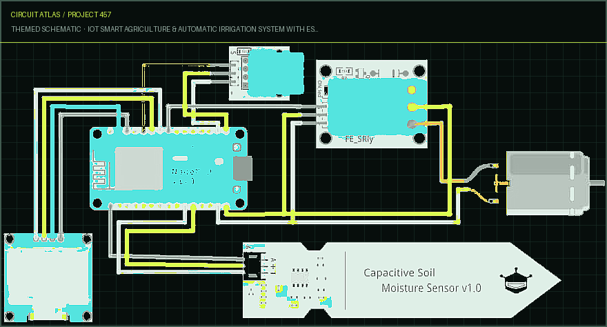
Project build noteLet's look at the project plan for the IoT Smart Agriculture and Automatic Irrigation System. For most of my projects, I use Fritzing to make a schematic. All you have to do is put something in place and connect it.
Setting Up Thingspeak Server
Project build noteNow we need to set up the account for Thingspeak. Follow these steps to
set up Thingspeak
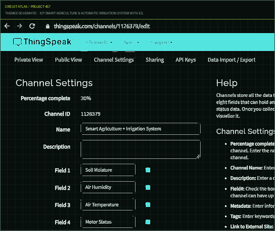
Project build noteStep 1: Go to https://thingspeak.com/ and fill out the information to make an account. Step 2: Make a new channel by clicking on "Channel" and filling in the following information, as shown in the image below.
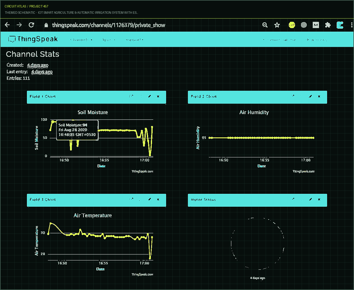
Step 3: Click on API Key. The "Write API Key" button will appear. Make a copy of the API Key. This is very important, and Code Part will need it. Step 4: You can click on "Private View" and change how the window looks to suit your needs.
Testing & Results This water pump must be completely covered with water. The pipe is kept in a field that needs watering. In the same way, the soil moisture sensor is put into the soil.
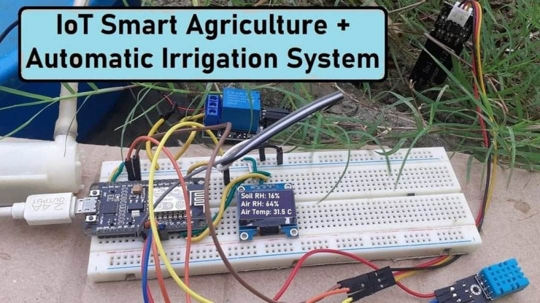
The OLED will start showing the Soil Humidity, Air Humidity, and Air Temperature as soon as you turn on the device. It shows the data as it is right now. When there isn't enough water in the soil, water pumps turn on and water the field until there is enough water. In the video below, you can see how it all works. With Thingspeak Server, you can look at the data online from anywhere in the world. To do that, you need to go to the Thingspeak server's private view. You can check the temperature, humidity, and moisture of the soil, as well as the status of the relay.
You built IoT Smart Agriculture & Automatic Irrigation System with ESP8266.
You followed the full workflow from understanding the mission to testing the finished project. That is a real engineering achievement - well done.
Home Automation using Google Firebase & NodeMCU ESP8266
Ready to reuse what you learned in another project from the same track?
Start this project →