IoT ECG Monitoring with AD8232 ECG Sensor & ESP8266
In this project, we will learn how to make an IoT-based ECG monitoring system using an AD8232 ECG sensor and a NodeMCU ESP8266. We will use an IoT platform called Ubidots to watch the ECG…
Know the mission before touching a wire.
Understand what you are making, prepare the right tools, and make the workbench safe.
Project details
IoT ECG Monitoring with AD8232 ECG Sensor & ESP8266 is a iot project. In this project, we will learn how to make an IoT-based ECG monitoring system using an AD8232 ECG sensor and a NodeMCU ESP8266. We will use an IoT platform called Ubidots to watch the ECG…
- Source pages
- 1205-1211
- Named parts
- 12
- Build goal
- Working, tested prototype
Tools you need
- Digital multimeter
- Wire stripper and side cutters
- Soldering iron with a fine tip
- Current-limited bench supply
- Computer with a data-capable USB cable
Use eye protection, good lighting, and a clean insulated surface throughout the build.
Safety precautions
- Disconnect every power source before changing a connection.
- Check component polarity, pinout, and supply voltage twice.
- Use a current limit for the first power-up.
- Keep liquids, loose metal, and uninsulated wires away from the bench.
Gather, identify, and understand every part.
Use the standardized inventory, then open What's this? to learn each part's role, advantages, limitations, handling, and specifications.
What's this?Image, role, pros, cons, handling & specifications
 MODULE LEARNING VIEW
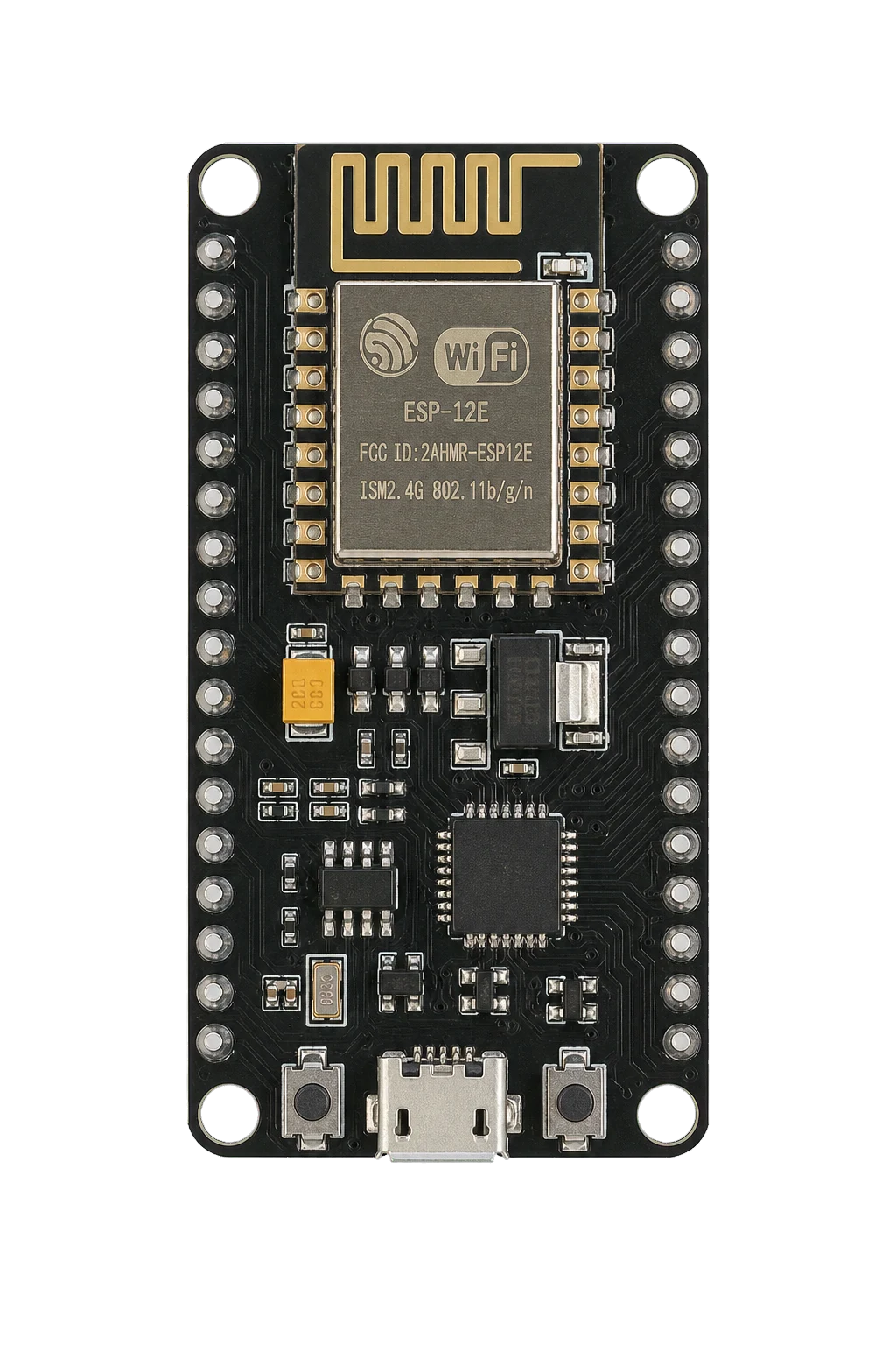
NodeMCU (ESP8266-12E Board)
A programmable controller that reads inputs, makes decisions, and drives the project's outputs.
What it does hereIt is the control centre and must use the documented board, pin map, supply, and logic level.
Buy / compare this part ↗Advantages
- Reprogrammable and reusable
- Large learning ecosystem
- Complex behaviour remains changeable
Limitations
- GPIO voltage and current are limited
- Some pins affect boot or communication
- Loads normally need a driver
Handling
- Disconnect power before rewiring
- Avoid static discharge
- Never power motors, relays, or pumps directly from GPIO
Specifications to verify
- Use the exact model, value, package, and rating listed for NodeMCU (ESP8266-12E Board); similar-looking parts are not always interchangeable.
- Confirm operating voltage, logic level, pinout, memory, USB interface, and maximum GPIO current.
What's this?Image, role, pros, cons, handling & specifications
ECG Sensor (AD8232 ECG Sensor Kit)
A sensor converts a physical condition into an electrical signal the circuit can measure.
What it does hereIt provides project input as an analogue, digital, resistive, frequency, or calibrated signal.
Buy / compare this part ↗Advantages
- Adds real-world awareness
- Can usually be tested independently
- Often supports calibration
Limitations
- Readings can drift
- Placement affects results
- Some sensors need warm-up or calibration
Handling
- Protect the sensing surface
- Observe supply voltage and polarity
- Keep signal leads away from noisy power wiring
Specifications to verify
- Use the exact model, value, package, and rating listed for ECG Sensor (AD8232 ECG Sensor Kit); similar-looking parts are not always interchangeable.
- Confirm supply range, output type, measurement range, accuracy, response time, and pin order.
What's this?Image, role, pros, cons, handling & specifications
Data Cable (5V Micro USB Data Cable)
A named project component whose exact role is defined by the source circuit and build guide.
What it does hereIt performs a documented electrical, control, interface, or construction function in this project.
Buy / compare this part ↗Advantages
- Selected for this project
- Can be checked independently
- Supports modular troubleshooting
Limitations
- Substitutes may differ
- Generic names can hide variants
- Pinouts and ratings vary
Handling
- Compare the received part with the source
- Keep it labelled
- Do not force connectors or adjusters
Specifications to verify
- Use the exact model, value, package, and rating listed for Data Cable (5V Micro USB Data Cable); similar-looking parts are not always interchangeable.
- Confirm dimensions, ratings, connection method, polarity, and environmental limits.
What's this?Image, role, pros, cons, handling & specifications
 POWER LEARNING VIEW
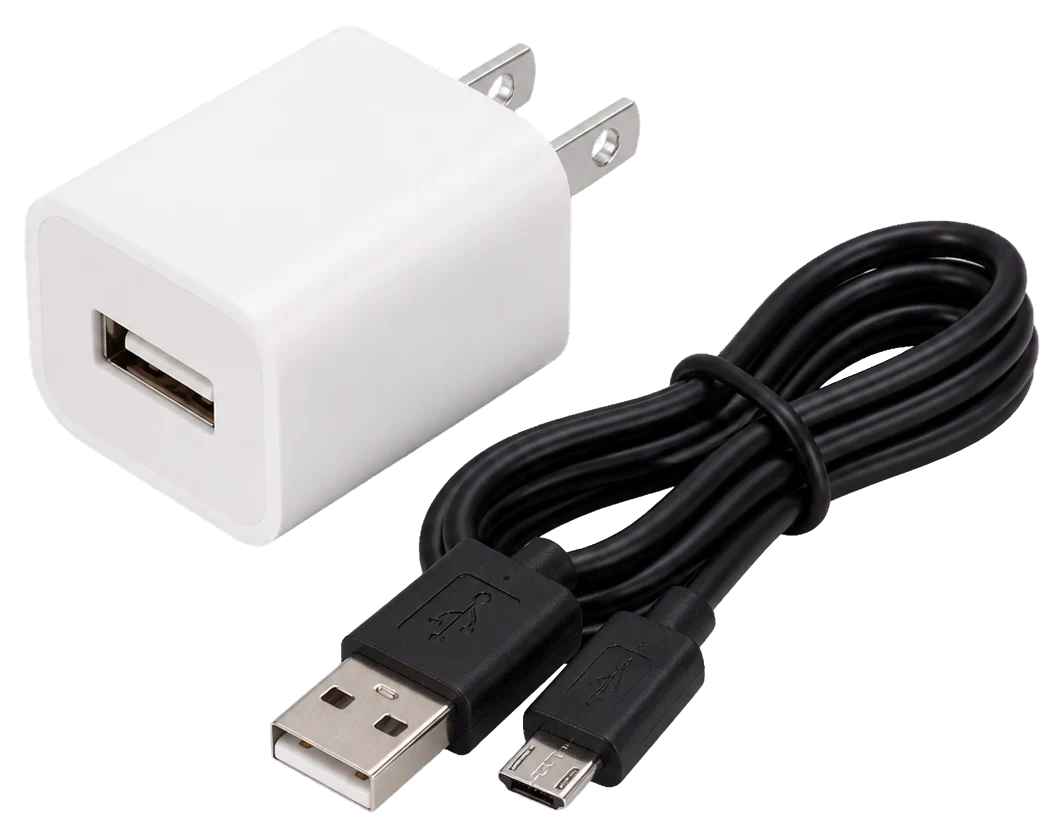
USB Adapter - 5V
A power component supplies, converts, stores, or regulates energy for the project.
What it does hereIt must provide the documented voltage, polarity, isolation, and sufficient current safely.
Buy / compare this part ↗Advantages
- Stable power improves reliability
- Current limiting protects first tests
- Regulation reduces resets and noise
Limitations
- Wrong polarity can cause immediate damage
- Underrated parts overheat
- Mains circuits require qualified supervision
Handling
- Measure output before connection
- Use a fuse or current limit
- Insulate exposed conductors
Specifications to verify
- Use the exact model, value, package, and rating listed for USB Adapter - 5V; similar-looking parts are not always interchangeable.
- Confirm input/output voltage, current, polarity, connector, isolation, and thermal rating.
What's this?Image, role, pros, cons, handling & specifications
ESP8266
A programmable controller that reads inputs, makes decisions, and drives the project's outputs.
What it does hereIt is the control centre and must use the documented board, pin map, supply, and logic level.
Buy / compare this part ↗Advantages
- Reprogrammable and reusable
- Large learning ecosystem
- Complex behaviour remains changeable
Limitations
- GPIO voltage and current are limited
- Some pins affect boot or communication
- Loads normally need a driver
Handling
- Disconnect power before rewiring
- Avoid static discharge
- Never power motors, relays, or pumps directly from GPIO
Specifications to verify
- Use the exact model, value, package, and rating listed for ESP8266; similar-looking parts are not always interchangeable.
- Confirm operating voltage, logic level, pinout, memory, USB interface, and maximum GPIO current.
What's this?Image, role, pros, cons, handling & specifications
ECG Leads/Electrode Placement
A named project component whose exact role is defined by the source circuit and build guide.
What it does hereIt performs a documented electrical, control, interface, or construction function in this project.
Buy / compare this part ↗Advantages
- Selected for this project
- Can be checked independently
- Supports modular troubleshooting
Limitations
- Substitutes may differ
- Generic names can hide variants
- Pinouts and ratings vary
Handling
- Compare the received part with the source
- Keep it labelled
- Do not force connectors or adjusters
Specifications to verify
- Use the exact model, value, package, and rating listed for ECG Leads/Electrode Placement; similar-looking parts are not always interchangeable.
- Confirm dimensions, ratings, connection method, polarity, and environmental limits.
What's this?Image, role, pros, cons, handling & specifications
Red: RA (Right Arm)
A named project component whose exact role is defined by the source circuit and build guide.
What it does hereIt performs a documented electrical, control, interface, or construction function in this project.
Buy / compare this part ↗Advantages
- Selected for this project
- Can be checked independently
- Supports modular troubleshooting
Limitations
- Substitutes may differ
- Generic names can hide variants
- Pinouts and ratings vary
Handling
- Compare the received part with the source
- Keep it labelled
- Do not force connectors or adjusters
Specifications to verify
- Use the exact model, value, package, and rating listed for Red: RA (Right Arm); similar-looking parts are not always interchangeable.
- Confirm dimensions, ratings, connection method, polarity, and environmental limits.
What's this?Image, role, pros, cons, handling & specifications
Yellow: LA (Left Arm)
A named project component whose exact role is defined by the source circuit and build guide.
What it does hereIt performs a documented electrical, control, interface, or construction function in this project.
Buy / compare this part ↗Advantages
- Selected for this project
- Can be checked independently
- Supports modular troubleshooting
Limitations
- Substitutes may differ
- Generic names can hide variants
- Pinouts and ratings vary
Handling
- Compare the received part with the source
- Keep it labelled
- Do not force connectors or adjusters
Specifications to verify
- Use the exact model, value, package, and rating listed for Yellow: LA (Left Arm); similar-looking parts are not always interchangeable.
- Confirm dimensions, ratings, connection method, polarity, and environmental limits.
What's this?Image, role, pros, cons, handling & specifications
Green: RL (Right Leg)
A named project component whose exact role is defined by the source circuit and build guide.
What it does hereIt performs a documented electrical, control, interface, or construction function in this project.
Buy / compare this part ↗Advantages
- Selected for this project
- Can be checked independently
- Supports modular troubleshooting
Limitations
- Substitutes may differ
- Generic names can hide variants
- Pinouts and ratings vary
Handling
- Compare the received part with the source
- Keep it labelled
- Do not force connectors or adjusters
Specifications to verify
- Use the exact model, value, package, and rating listed for Green: RL (Right Leg); similar-looking parts are not always interchangeable.
- Confirm dimensions, ratings, connection method, polarity, and environmental limits.
What's this?Image, role, pros, cons, handling & specifications
Result & Observations
A named project component whose exact role is defined by the source circuit and build guide.
What it does hereIt performs a documented electrical, control, interface, or construction function in this project.
Buy / compare this part ↗Advantages
- Selected for this project
- Can be checked independently
- Supports modular troubleshooting
Limitations
- Substitutes may differ
- Generic names can hide variants
- Pinouts and ratings vary
Handling
- Compare the received part with the source
- Keep it labelled
- Do not force connectors or adjusters
Specifications to verify
- Use the exact model, value, package, and rating listed for Result & Observations; similar-looking parts are not always interchangeable.
- Confirm dimensions, ratings, connection method, polarity, and environmental limits.
What's this?Image, role, pros, cons, handling & specifications
IoT based ECG Monitoring with AD8232 ECG Sensor & ESP8266
A programmable controller that reads inputs, makes decisions, and drives the project's outputs.
What it does hereIt is the control centre and must use the documented board, pin map, supply, and logic level.
Buy / compare this part ↗Advantages
- Reprogrammable and reusable
- Large learning ecosystem
- Complex behaviour remains changeable
Limitations
- GPIO voltage and current are limited
- Some pins affect boot or communication
- Loads normally need a driver
Handling
- Disconnect power before rewiring
- Avoid static discharge
- Never power motors, relays, or pumps directly from GPIO
Specifications to verify
- Use the exact model, value, package, and rating listed for IoT based ECG Monitoring with AD8232 ECG Sensor & ESP8266; similar-looking parts are not always interchangeable.
- Confirm operating voltage, logic level, pinout, memory, USB interface, and maximum GPIO current.
What's this?Image, role, pros, cons, handling & specifications
Results & Observations
A named project component whose exact role is defined by the source circuit and build guide.
What it does hereIt performs a documented electrical, control, interface, or construction function in this project.
Buy / compare this part ↗Advantages
- Selected for this project
- Can be checked independently
- Supports modular troubleshooting
Limitations
- Substitutes may differ
- Generic names can hide variants
- Pinouts and ratings vary
Handling
- Compare the received part with the source
- Keep it labelled
- Do not force connectors or adjusters
Specifications to verify
- Use the exact model, value, package, and rating listed for Results & Observations; similar-looking parts are not always interchangeable.
- Confirm dimensions, ratings, connection method, polarity, and environmental limits.
Connect one verified path at a time.
Explore the named components and standardized signal flow, then use Source Check to verify exact physical pins, values, and topology before applying power.
Trace this circuit.
IoT ECG Monitoring with AD8232 ECG Sensor & ESP8266: interactive parts, standardized terminals, responsive anchored wires, student explanations, and the original circuit reference in one shared system.
Trace before wiring
Follow power, ground, inputs, processing, and outputs in that order. Never guess a pin from package shape alone.
Connect with power off
Make short, labelled connections and share a common ground only where the schematic requires it.
Inspect every joint
Check continuity, polarity, adjacent shorts, and loose connections before the first power-up.
Open all source diagrams and build views 6 visuals
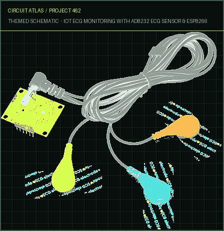
Confirm the hardware-only control path.
This project does not include firmware in the source. The circuit itself provides the required behaviour.
How to connect
- Match every controller label to the circuit view and source pin map.
- Join grounds before signal wires when separate low-voltage supplies are used.
- Keep motors, relays, pumps, and other loads on a suitable driver and external supply.
Common mistakes
Reversed VCC/GND, board-label versus GPIO-number confusion, missing common ground, and charge-only USB cables.
Troubleshoot
Disconnect loads, continuity-test one path at a time, then test with a current limit.
Software preparation
No IDE, board package, library, or firmware upload is required for this project.
If you add a programmable controller as an extension, document its pin map separately.
How to upload code
The original design is implemented entirely in hardware, so proceed after verifying the circuit and supply.
Assemble, deploy, test, and troubleshoot.
Use the complete source notes in build order, then pass the final checks before calling the project finished.
Build in functional stages
- Power and regulation
- Controller or processing stage
- Inputs and sensors
- Outputs and loads
- Enclosure and strain relief
Power up safely
- Inspect unpowered continuity first
- Apply the lowest safe current limit
- Measure supply rails before signals
- Add one load at a time
- Record expected and actual results
Work from simple to complex
- Confirm power, ground, polarity, and orientation
- Compare each pin with the source
- Test inputs separately from outputs
- Replace only one variable at a time
- Power off before every correction
Follow the documented instructions.
These notes come from this project's source and remain in their original order.
Project overview
Project build noteIn this project, we will learn how to make an IoT-based ECG monitoring system using an AD8232 ECG sensor and a NodeMCU ESP8266. We will use an IoT platform called Ubidots to watch the ECG waveform/Graph made by the AD8232 Sensor online.
In the last few decades, heart diseases have become a big problem, and many people die because of health problems. So, heart disease is not something to be taken lightly. So, there should be a technology that can keep an eye on the patient's heart rate and how it works. By analyzing or keeping an eye on the ECG signal early on, different types of heart disease can be avoided. This is why I'm showing you this great Internet of Things (IoT) project. In this project, I'll show you how to connect the AD8232 ECG Sensor to the NodeMCU ESP8266 Board and watch the ECG Waveform on the Serial Plotter Screen. In the same way, you can send the ECG waveform over the IoT Cloud platform and monitor the signal online using a PC or a smartphone from anywhere in the world. If you want to watch your heart's activity or behavior, you don't have to stay in the hospital. You can do it online from anywhere. So, it can be said that the Patient Health Monitoring System has made progress. The IoT platform that I am gonna use here is Ubidots. Ubidots is an Internet of Things (IoT) platform that lets innovators and businesses build
prototypes of IoT projects and scale them up to make them. You can send data to the cloud from any device that can connect to the Internet by using the Ubidots platform. Then, you can set up actions and alerts based on your real-time data and use visual tools to get the most out of your data. AD8232 ECG Sensor This sensor is a cheap board that is used to measure the heart's electrical activity. This electrical activity can be charted as an ECG or Electrocardiogram and output as an analog reading. ECGs can be extremely noisy, the AD8232 Single Lead Heart Rate Monitor acts as an op-amp to help obtain a clear signal from the PR and QT Intervals easily. The AD8232 is a built-in signal conditioning block that can be used to measure ECG and other biopotentials. It is made to find, boost, and filter small biopotential signals even when there is a lot of noise, like when the electrodes are moved or placed far away. The AD8232 module breaks out nine connections from the IC that you can solder pins, wires, or other connectors to. This monitor can be used with an Arduino or other development board through its SDN, LO+, LO-, OUTPUT, 3.3V, and GND pins. There are also RA (Right Arm), LA (Left
Arm), and RL (Right Leg) pins on this board so you can attach and use your own custom sensors. There is also an LED indicator light that pulses to the beat of your heart. Note: This product is NOT a medical device, and it is not meant to be used as one or as a part of one. It is also not meant to be used to diagnose or treat any health problems.
Component Required
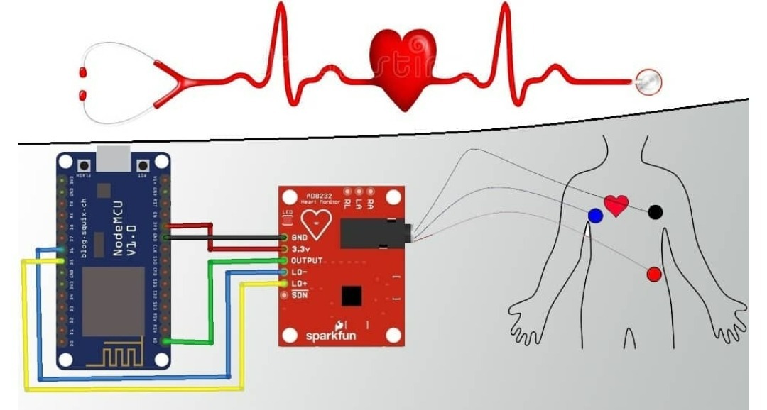
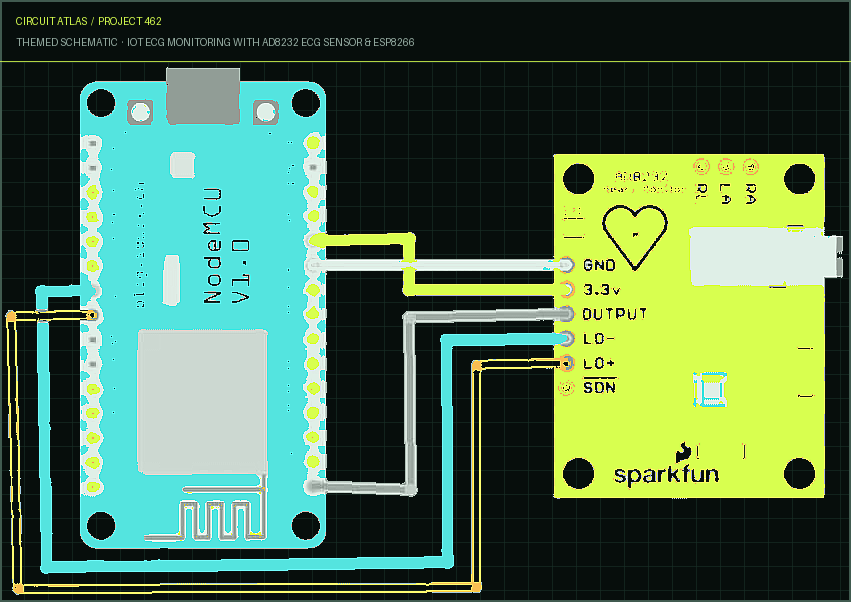
Project build noteNodeMCU (ESP8266-12E Board) ECG Sensor (AD8232 ECG Sensor Kit) Data Cable (5V Micro USB Data Cable) USB Adapter - 5V Breadboard Circuit Diagram: Interfacing AD8232 ECG Sensor with NodeMCU ESP8266 Here is a diagram of how to connect the NodeMCU ESP8266 to the AD8232 ECG sensor. AD8232 Breakout Board has six pins. SDN is not linked together.
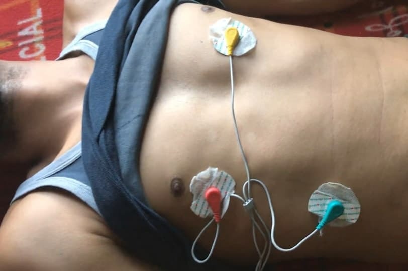
Connect the OUTPUT to Nodemcu's analog A0. Connect the LO+ and LO- wires to NodeMCU's D5 and D6. Give the AD8232 kit 3.3V VCC and connect its GND to the GND on the kit. ECG Leads/Electrode Placement It is recommended to snap the sensor pads on the leads before application to the body. The better the reading, the closer the pads are to the heart. The cables are color-coded to help identify proper placement. Red: RA (Right Arm) Yellow: LA (Left Arm) Green: RL (Right Leg) We connected an ESP8266 with an AD8232 to a patient chest, or you can just put it in your chest, as shown in the figure picture. Result & Observations
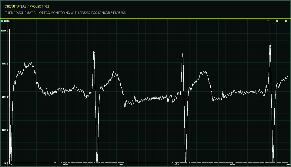
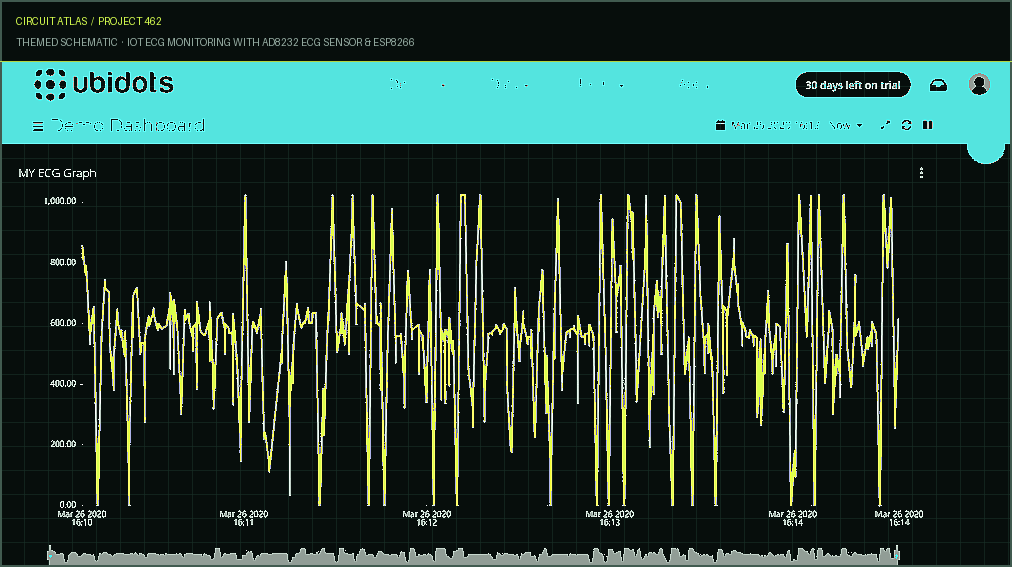
Open the Serial Monitor and set the Buad Rate to 9600 once the code is uploaded. As a visualization effect on Serial Monitor, the ECG waveform can be seen in the next image. IoT based ECG Monitoring with AD8232 ECG Sensor & ESP8266 With the code shown above, you can see the ECG waveform on the Serial Plotter Screen. Now, though, we want to be able to see the ECG waveform from anywhere in the world. So, I won't have to send the signal to any IoT platform for that. I did that with Ubidots. With Ubidots, you can send information to the cloud from any device that can connect to the Internet. Results & Observations After you upload the code, you can open the serial Monitor. If the module is connected to WiFi and Ubidot's token is valid, the Serial Monitor will show the following lines.
You can now go to the Ubidots dashboard and watch the waveform get posted on Ubidots. Due to a small amount of delay, the waveform may not look exactly like the one above. But it's enough to show something simple. In the near future, the device can be made in a better way.
You built IoT ECG Monitoring with AD8232 ECG Sensor & ESP8266.
You followed the full workflow from understanding the mission to testing the finished project. That is a real engineering achievement - well done.
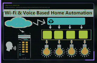
ESP8266 and Android Home Automation with WiFi and Voice Control
Ready to reuse what you learned in another project from the same track?
Start this project →