Alexa (Echo) with ESP32 and ESP8266 - Voice Controlled Relay
You are going to learn how to give voice commands to Alexa in order to control an ESP8266 or an ESP32 device with the help of this project (Amazon Echo Dot). We'll demonstrate how to cont…
Know the mission before touching a wire.
Understand what you are making, prepare the right tools, and make the workbench safe.
Project details
Alexa (Echo) with ESP32 and ESP8266 - Voice Controlled Relay is a iot project. You are going to learn how to give voice commands to Alexa in order to control an ESP8266 or an ESP32 device with the help of this project (Amazon Echo Dot). We'll demonstrate how to cont…
- Source pages
- 1313-1322
- Named parts
- 4
- Build goal
- Working, tested prototype
Tools you need
- Digital multimeter
- Wire stripper and side cutters
- Soldering iron with a fine tip
- Current-limited bench supply
- Computer with a data-capable USB cable
Use eye protection, good lighting, and a clean insulated surface throughout the build.
Safety precautions
- Disconnect every power source before changing a connection.
- Check component polarity, pinout, and supply voltage twice.
- Use a current limit for the first power-up.
- Keep liquids, loose metal, and uninsulated wires away from the bench.
Gather, identify, and understand every part.
Use the standardized inventory, then open What's this? to learn each part's role, advantages, limitations, handling, and specifications.
What's this?Image, role, pros, cons, handling & specifications
ESP8266
A programmable controller that reads inputs, makes decisions, and drives the project's outputs.
What it does hereIt is the control centre and must use the documented board, pin map, supply, and logic level.
Buy / compare this part ↗Advantages
- Reprogrammable and reusable
- Large learning ecosystem
- Complex behaviour remains changeable
Limitations
- GPIO voltage and current are limited
- Some pins affect boot or communication
- Loads normally need a driver
Handling
- Disconnect power before rewiring
- Avoid static discharge
- Never power motors, relays, or pumps directly from GPIO
Specifications to verify
- Use the exact model, value, package, and rating listed for ESP8266; similar-looking parts are not always interchangeable.
- Confirm operating voltage, logic level, pinout, memory, USB interface, and maximum GPIO current.
What's this?Image, role, pros, cons, handling & specifications
ESP32
A programmable controller that reads inputs, makes decisions, and drives the project's outputs.
What it does hereIt is the control centre and must use the documented board, pin map, supply, and logic level.
Buy / compare this part ↗Advantages
- Reprogrammable and reusable
- Large learning ecosystem
- Complex behaviour remains changeable
Limitations
- GPIO voltage and current are limited
- Some pins affect boot or communication
- Loads normally need a driver
Handling
- Disconnect power before rewiring
- Avoid static discharge
- Never power motors, relays, or pumps directly from GPIO
Specifications to verify
- Use the exact model, value, package, and rating listed for ESP32; similar-looking parts are not always interchangeable.
- Confirm operating voltage, logic level, pinout, memory, USB interface, and maximum GPIO current.
What's this?Image, role, pros, cons, handling & specifications
Relay module
An output component turns an electrical control signal into light, sound, motion, switching, or displayed information.
What it does hereIt presents the circuit result or acts on the physical world.
Buy / compare this part ↗Advantages
- Makes system state visible
- Can be tested separately
- Supports clear troubleshooting
Limitations
- Loads may exceed controller current
- Polarity or driver direction can matter
- Inductive loads create voltage spikes
Handling
- Use the documented driver stage
- Check polarity and load current
- Add flyback protection for inductive loads
Specifications to verify
- Use the exact model, value, package, and rating listed for Relay module; similar-looking parts are not always interchangeable.
- Confirm voltage, current, polarity, interface, driver requirements, and duty cycle.
What's this?Image, role, pros, cons, handling & specifications
Transformer
A power component supplies, converts, stores, or regulates energy for the project.
What it does hereIt must provide the documented voltage, polarity, isolation, and sufficient current safely.
Buy / compare this part ↗Advantages
- Stable power improves reliability
- Current limiting protects first tests
- Regulation reduces resets and noise
Limitations
- Wrong polarity can cause immediate damage
- Underrated parts overheat
- Mains circuits require qualified supervision
Handling
- Measure output before connection
- Use a fuse or current limit
- Insulate exposed conductors
Specifications to verify
- Use the exact model, value, package, and rating listed for Transformer; similar-looking parts are not always interchangeable.
- Confirm input/output voltage, current, polarity, connector, isolation, and thermal rating.
Connect one verified path at a time.
Explore the named components and standardized signal flow, then use Source Check to verify exact physical pins, values, and topology before applying power.
Trace this circuit.
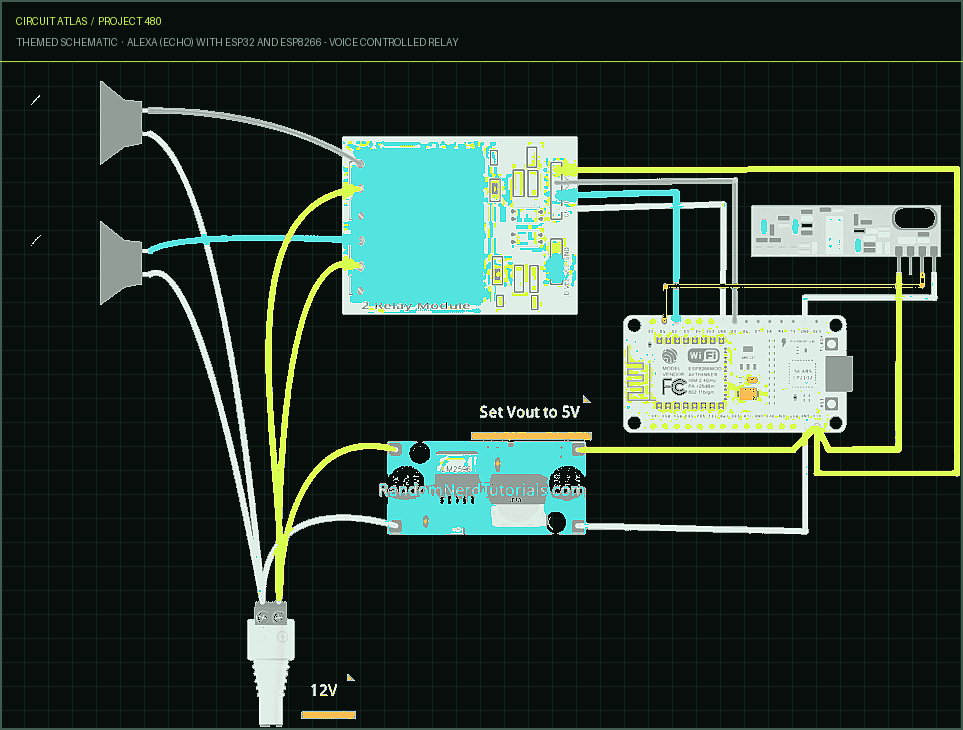
Alexa (Echo) with ESP32 and ESP8266 - Voice Controlled Relay: interactive parts, standardized terminals, responsive anchored wires, student explanations, and the original circuit reference in one shared system.
Trace before wiring
Follow power, ground, inputs, processing, and outputs in that order. Never guess a pin from package shape alone.
Connect with power off
Make short, labelled connections and share a common ground only where the schematic requires it.
Inspect every joint
Check continuity, polarity, adjacent shorts, and loose connections before the first power-up.
Open all source diagrams and build views 7 visuals
Confirm the hardware-only control path.
This project does not include firmware in the source. The circuit itself provides the required behaviour.
How to connect
- Match every controller label to the circuit view and source pin map.
- Join grounds before signal wires when separate low-voltage supplies are used.
- Keep motors, relays, pumps, and other loads on a suitable driver and external supply.
Common mistakes
Reversed VCC/GND, board-label versus GPIO-number confusion, missing common ground, and charge-only USB cables.
Troubleshoot
Disconnect loads, continuity-test one path at a time, then test with a current limit.
Software preparation
No IDE, board package, library, or firmware upload is required for this project.
If you add a programmable controller as an extension, document its pin map separately.
How to upload code
The original design is implemented entirely in hardware, so proceed after verifying the circuit and supply.
Assemble, deploy, test, and troubleshoot.
Use the complete source notes in build order, then pass the final checks before calling the project finished.
Build in functional stages
- Power and regulation
- Controller or processing stage
- Inputs and sensors
- Outputs and loads
- Enclosure and strain relief
Power up safely
- Inspect unpowered continuity first
- Apply the lowest safe current limit
- Measure supply rails before signals
- Add one load at a time
- Record expected and actual results
Work from simple to complex
- Confirm power, ground, polarity, and orientation
- Compare each pin with the source
- Test inputs separately from outputs
- Replace only one variable at a time
- Power off before every correction
Follow the documented instructions.
These notes come from this project's source and remain in their original order.
Project overview
Project build noteYou are going to learn how to give voice commands to Alexa in order to control an ESP8266 or an ESP32 device with the help of this project (Amazon Echo Dot). We'll demonstrate how to control relays by manipulating two 12V lamps that are connected to a relay module. In addition to this, we will install two 433 MHz RF wall panel switches so that the lamps can be physically controlled. Note: this tutorial is compatible with all Echo Dot generations and with the latest fauxmoESP library (3.1.0). It is compatible with both the ESP32 and the ESP8266.
Project Overview
Project build noteThis project is compatible with the ESP8266 as well as the ESP32. Instructions are provided by us for both of the development boards. Read the rest of this section first so that you have an idea of what you will have accomplished by the time you are finished with this project. Alexa can be used to control the Lamps.
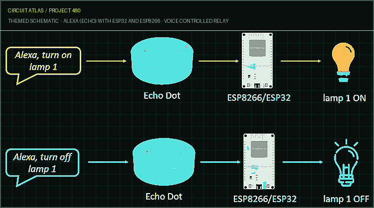
When you are finished with this project, you will be able to use voice commands to control two lamps (lamp 1 and lamp 2) that are controlled by Alexa. The diagram that follows provides a high-level overview of how the project operates to control lamp 1; it operates in a comparable manner for lamp 2.
The following are the commands that Alexa will respond to
Project build note"Alexa, turn on lamp 1" "Alexa, switch off the first lamp." "Alexa, turn on lamp 2" "Alexa, turn on lamp 2" When you tell Alexa to "turn on lamps," she turns on both of them. When you tell Alexa to turn off the lamps, both of them turn off. A relay will be triggered by the ESP8266 or ESP32 whenever you say something like, "Alexa, turn on lamp 1." This will cause lamp 1 to turn on. When you tell Alexa to do something like "turn off lamp 1," either the
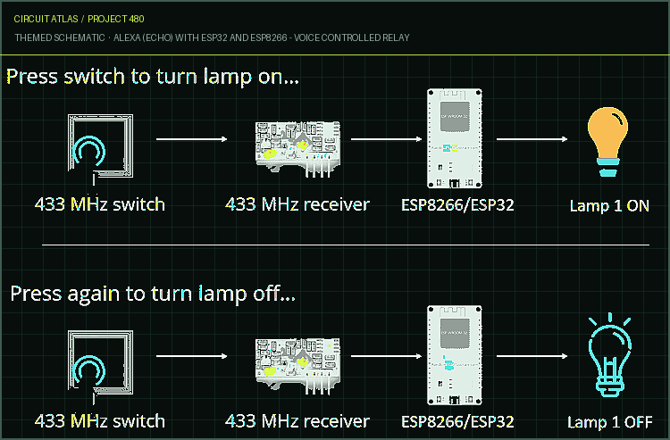
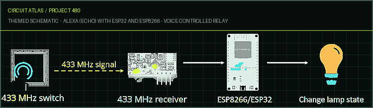
ESP8266 or the ESP32 will send a signal to the relay, which will cause the lamp to turn off. Lamp 2 operates in a manner analogous to this. Wall Switches Operating at 433 MHz Used to Regulate Lamps As part of this project, we will also install two wall switches that operate at 433 MHz in order to physically control the lamps. Each lamp will have its own separate switch. The state of the lamp is altered by the switch so that it becomes the opposite of what it was previously. For instance, if the lamp is turned off, you can turn it on by pressing the wall switch. Simply pressing the switch once more will cause it to be turned off. Take a look at the diagram that is provided below; it shows how the process works.
Parts Required
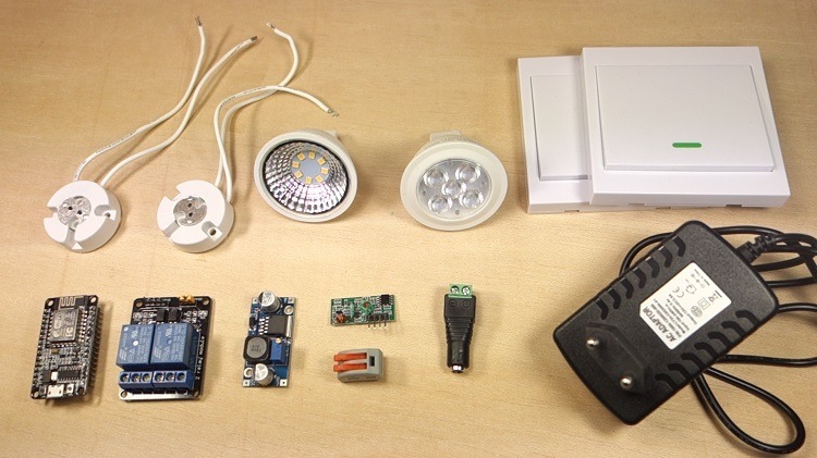
Project build noteThis is a comprehensive list of all of the components that are needed for this project. ESP Board (you have the option of using either an ESP32 or an
ESP8266)
Project build noteESP8266: for more information, see the article titled Best ESP8266 Wi-Fi Development Boards ESP32, for which we make use of the ESP32 DOIT DEVKIT V1 Board, which has a total of 36 GPIOs (read ESP32 development boards comparison) Alexa, available on the Echo, Echo Show, and Echo Dot (read the next section for more details) RF Wall Panel Switch 433 MHz 433 MHz Transmitter and Receiver 12V 2A Power Adaptor buck converter with a step-down transformer Relay module 12V lamp 12V lamp holder Male DC barrel jack 2.1mm Stripboard or breadboard A set of jumper wires
RF Wall Panel Switch Operating at 433 MHz A fantastic tool for exercising remote control over electronic devices is the 433 MHz RF wall panel switch. It is possible to quickly and easily attach it to a wall using adhesive tape, eliminating the need to drill holes in the walls. In addition to this, it is wireless, which means that you do not have to worry about wiring it or hiding the cables afterwards. We are making use of two wall panel switches for this particular project. You could, alternatively, use a panel switch that has two buttons; there is also another version of this switch that has three buttons. As can be seen in the illustration to the right, this wall panel switch's circuit includes a push button that, when pressed, sends out a signal at a frequency of 433 MHz. You are free to control whatever you like with the help of that signal. The battery that powers this wall panel switch is a 27A 12V type (not included in the package). As a result, you should probably get one when you get the switch for the wall panel. Decode the Wall Panel Switch 433 MHz RF Signals A signal at 433 MHz is transmitted whenever the switch on the 433 MHz wall panel is pressed. You will need to make use of a 433 MHz receiver in order to decode that signal. Read the following post to acquire the knowledge necessary to decode the 433 MHz signal: Read the "Decoder Sketch" section to learn how to use Arduino to decode and send RF signals at 433 MHz. This sketch can be run on Arduino as well as ESP32 and ESP8266. It is important to make a note of the decimal (24-bit) code for each of your switches, as you will require it at a later time.
In my case
Project build note6819768 on switch 1; 9463928 on switch 2 You should get different values. After that, you will implement these signals into the sketch for your ESP8266 or ESP32. When the switch is pressed, it will send a signal at a frequency of 433 MHz. The receiver that is linked to the ESP is able to pick up on the presence of this signal. Because of this, the ESP is aware that the switch was pressed, and it adjusts the state of the lamp accordingly. The FauxmoESP You will need to have the FauxmoESP library installed in order to control your ESP8266 or ESP32 with Amazon Echo. By using this library, which simulates a Belkin Wemo device, you will be able to control your ESP32 or ESP8266 using the protocol developed by Belkin. After the code has been uploaded, the Echo or Echo Dot will be able to instantly recognize the device without the need for any additional expertise or services from a third party. Download the FauxmoESP library, click, Within your Downloads folder, you ought to have a.zip folder. After unzipping the.zip folder, you should find the xoseperez- fauxmoesp-50cbcf3087fd folder in the directory that you just created.
Rename your folder from xoseperez-fauxmoesp-50cbcf3087fd to xoseperez fauxmoesp Transfer the xoseperez fauxmoesp folder to the libraries folder that was created during the installation of your Arduino IDE. Finally, reopen the Arduino integrated development environment (IDE) for the Alexa–Echo Dot with ESP8266. If you are utilizing an ESP8266, proceed with the following instructions. Installing the ESP8266 Board in Arduino IDE Installing an add-on for the Arduino IDE that enables you to program the ESP8266 using the Arduino IDE and its programming language is required before you can use the Arduino IDE to upload code to your ESP8266 device. The add-on can be found on the Arduino website. If you haven't already, you should download and install the ESP8266 extension for the Arduino IDE.
Installing the ESPAsyncTCP Library 1. In addition to that, the ESPAsyncTCP Library library needs to be installed. To install it, just make sure to follow these instructions: 2. To download the ESPAsyncTCP library, click on the link provided. Within your Downloads folder, you ought to have a.zip folder. 3. After unzipping the.zip folder, you should see a folder labeled ESPAsyncTCP-master. 4. Change the name of your folder to ESPAsyncTCP instead of ESPAsyncTCP-master.
5. Place the ESPAsyncTCP folder inside the libraries folder that was installed with your Arduino IDE. 6. Finally, reopen the schematic file in your Arduino IDE.
Circuit Diagram
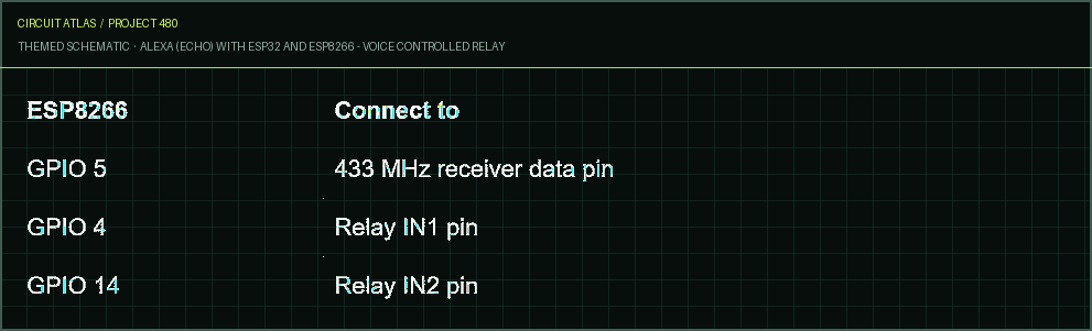
Project build noteIf you are putting together your circuit using an ESP8266 board, the following schematic diagram should be followed. You can click the image to see it in greater detail. The information in the following table can serve as a reference for you if you're having trouble understanding the circuit diagram
Demonstration
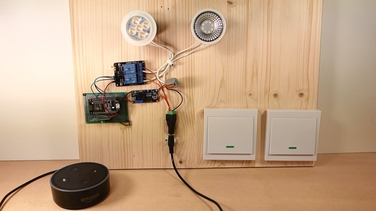
Project build noteAs a demonstration of our work, we have constructed our circuit on a prototyping stripboard and attached all of the components to a wooden
board, as can be seen in the figure below
Project build noteNow you can ask Alexa to control your lamps with the following voice
commands
Project build note"Alexa, turn on lamp 1" "Alexa, switch off the first lamp." "Alexa, turn on lamp 2" "Alexa, turn on lamp 2"
If you create a group in the Amazon Alexa app, you will also have the ability to control both lamps at the same time. We referred to them as "lamps." You are now capable of controlling both lamps at the same time using the voice commands that are listed below. "Alexa, turn on lamps" "Alexa, switch off the lights." The wall panel switches that use the 433 MHz frequency can also be used to physically control your lamps. In this project, we demonstrated how to use voice commands to control both your ESP8266 and your ESP32 devices using Amazon Echo. As an illustration, we have utilized a relay in order to control two 12V lamps. You are not limited to just controlling 12V lamps; you can do so with any other electronic appliance. We have also demonstrated how you can utilize a 433 MHz wall panel switch to exercise remote control over your lighting fixtures.
You built Alexa (Echo) with ESP32 and ESP8266 - Voice Controlled Relay.
You followed the full workflow from understanding the mission to testing the finished project. That is a real engineering achievement - well done.
How the HC-SR04 Ultrasonic Range Sensor Can Communicate with the ESP32
Ready to reuse what you learned in another project from the same track?
Start this project →