How the HC-SR04 Ultrasonic Range Sensor Can Communicate with the ESP32
with the ESP32 If you want to build a robot that can avoid obstacles but are just starting out as an electronics engineer, the first thing you need to do is educate yourself on how an obs…
Know the mission before touching a wire.
Understand what you are making, prepare the right tools, and make the workbench safe.
Project details
How the HC-SR04 Ultrasonic Range Sensor Can Communicate with the ESP32 is a iot project. with the ESP32 If you want to build a robot that can avoid obstacles but are just starting out as an electronics engineer, the first thing you need to do is educate yourself on how an obs…
- Source pages
- 1322-1329
- Named parts
- 9
- Build goal
- Working, tested prototype
Tools you need
- Digital multimeter
- Wire stripper and side cutters
- Soldering iron with a fine tip
- Current-limited bench supply
- Computer with a data-capable USB cable
Use eye protection, good lighting, and a clean insulated surface throughout the build.
Safety precautions
- Disconnect every power source before changing a connection.
- Check component polarity, pinout, and supply voltage twice.
- Use a current limit for the first power-up.
- Keep liquids, loose metal, and uninsulated wires away from the bench.
Gather, identify, and understand every part.
Use the standardized inventory, then open What's this? to learn each part's role, advantages, limitations, handling, and specifications.
What's this?Image, role, pros, cons, handling & specifications
ESP8266
A programmable controller that reads inputs, makes decisions, and drives the project's outputs.
What it does hereIt is the control centre and must use the documented board, pin map, supply, and logic level.
Buy / compare this part ↗Advantages
- Reprogrammable and reusable
- Large learning ecosystem
- Complex behaviour remains changeable
Limitations
- GPIO voltage and current are limited
- Some pins affect boot or communication
- Loads normally need a driver
Handling
- Disconnect power before rewiring
- Avoid static discharge
- Never power motors, relays, or pumps directly from GPIO
Specifications to verify
- Use the exact model, value, package, and rating listed for ESP8266; similar-looking parts are not always interchangeable.
- Confirm operating voltage, logic level, pinout, memory, USB interface, and maximum GPIO current.
What's this?Image, role, pros, cons, handling & specifications
ESP32
A programmable controller that reads inputs, makes decisions, and drives the project's outputs.
What it does hereIt is the control centre and must use the documented board, pin map, supply, and logic level.
Buy / compare this part ↗Advantages
- Reprogrammable and reusable
- Large learning ecosystem
- Complex behaviour remains changeable
Limitations
- GPIO voltage and current are limited
- Some pins affect boot or communication
- Loads normally need a driver
Handling
- Disconnect power before rewiring
- Avoid static discharge
- Never power motors, relays, or pumps directly from GPIO
Specifications to verify
- Use the exact model, value, package, and rating listed for ESP32; similar-looking parts are not always interchangeable.
- Confirm operating voltage, logic level, pinout, memory, USB interface, and maximum GPIO current.
What's this?Image, role, pros, cons, handling & specifications
Ultrasonic sensor
A sensor converts a physical condition into an electrical signal the circuit can measure.
What it does hereIt provides project input as an analogue, digital, resistive, frequency, or calibrated signal.
Buy / compare this part ↗Advantages
- Adds real-world awareness
- Can usually be tested independently
- Often supports calibration
Limitations
- Readings can drift
- Placement affects results
- Some sensors need warm-up or calibration
Handling
- Protect the sensing surface
- Observe supply voltage and polarity
- Keep signal leads away from noisy power wiring
Specifications to verify
- Use the exact model, value, package, and rating listed for Ultrasonic sensor; similar-looking parts are not always interchangeable.
- Confirm supply range, output type, measurement range, accuracy, response time, and pin order.
What's this?Image, role, pros, cons, handling & specifications
HC-SR04
A named project component whose exact role is defined by the source circuit and build guide.
What it does hereIt performs a documented electrical, control, interface, or construction function in this project.
Buy / compare this part ↗Advantages
- Selected for this project
- Can be checked independently
- Supports modular troubleshooting
Limitations
- Substitutes may differ
- Generic names can hide variants
- Pinouts and ratings vary
Handling
- Compare the received part with the source
- Keep it labelled
- Do not force connectors or adjusters
Specifications to verify
- Use the exact model, value, package, and rating listed for HC-SR04; similar-looking parts are not always interchangeable.
- Confirm dimensions, ratings, connection method, polarity, and environmental limits.
What's this?Image, role, pros, cons, handling & specifications
HC-PINOUT
A named project component whose exact role is defined by the source circuit and build guide.
What it does hereIt performs a documented electrical, control, interface, or construction function in this project.
Buy / compare this part ↗Advantages
- Selected for this project
- Can be checked independently
- Supports modular troubleshooting
Limitations
- Substitutes may differ
- Generic names can hide variants
- Pinouts and ratings vary
Handling
- Compare the received part with the source
- Keep it labelled
- Do not force connectors or adjusters
Specifications to verify
- Use the exact model, value, package, and rating listed for HC-PINOUT; similar-looking parts are not always interchangeable.
- Confirm dimensions, ratings, connection method, polarity, and environmental limits.
What's this?Image, role, pros, cons, handling & specifications
HC-RANGE
A named project component whose exact role is defined by the source circuit and build guide.
What it does hereIt performs a documented electrical, control, interface, or construction function in this project.
Buy / compare this part ↗Advantages
- Selected for this project
- Can be checked independently
- Supports modular troubleshooting
Limitations
- Substitutes may differ
- Generic names can hide variants
- Pinouts and ratings vary
Handling
- Compare the received part with the source
- Keep it labelled
- Do not force connectors or adjusters
Specifications to verify
- Use the exact model, value, package, and rating listed for HC-RANGE; similar-looking parts are not always interchangeable.
- Confirm dimensions, ratings, connection method, polarity, and environmental limits.
What's this?Image, role, pros, cons, handling & specifications
MAXIMUM
A named project component whose exact role is defined by the source circuit and build guide.
What it does hereIt performs a documented electrical, control, interface, or construction function in this project.
Buy / compare this part ↗Advantages
- Selected for this project
- Can be checked independently
- Supports modular troubleshooting
Limitations
- Substitutes may differ
- Generic names can hide variants
- Pinouts and ratings vary
Handling
- Compare the received part with the source
- Keep it labelled
- Do not force connectors or adjusters
Specifications to verify
- Use the exact model, value, package, and rating listed for MAXIMUM; similar-looking parts are not always interchangeable.
- Confirm dimensions, ratings, connection method, polarity, and environmental limits.
What's this?Image, role, pros, cons, handling & specifications
NEWPING
A named project component whose exact role is defined by the source circuit and build guide.
What it does hereIt performs a documented electrical, control, interface, or construction function in this project.
Buy / compare this part ↗Advantages
- Selected for this project
- Can be checked independently
- Supports modular troubleshooting
Limitations
- Substitutes may differ
- Generic names can hide variants
- Pinouts and ratings vary
Handling
- Compare the received part with the source
- Keep it labelled
- Do not force connectors or adjusters
Specifications to verify
- Use the exact model, value, package, and rating listed for NEWPING; similar-looking parts are not always interchangeable.
- Confirm dimensions, ratings, connection method, polarity, and environmental limits.
What's this?Image, role, pros, cons, handling & specifications
ESP8266-12E - controller board / IC
A programmable controller that reads inputs, makes decisions, and drives the project's outputs.
What it does hereIt is the control centre and must use the documented board, pin map, supply, and logic level.
Buy / compare this part ↗Advantages
- Reprogrammable and reusable
- Large learning ecosystem
- Complex behaviour remains changeable
Limitations
- GPIO voltage and current are limited
- Some pins affect boot or communication
- Loads normally need a driver
Handling
- Disconnect power before rewiring
- Avoid static discharge
- Never power motors, relays, or pumps directly from GPIO
Specifications to verify
- Use the exact model, value, package, and rating listed for ESP8266-12E - controller board / IC; similar-looking parts are not always interchangeable.
- Confirm operating voltage, logic level, pinout, memory, USB interface, and maximum GPIO current.
Connect one verified path at a time.
Explore the named components and standardized signal flow, then use Source Check to verify exact physical pins, values, and topology before applying power.
Trace this circuit.
How the HC-SR04 Ultrasonic Range Sensor Can Communicate with the ESP32: interactive parts, standardized terminals, responsive anchored wires, student explanations, and the original circuit reference in one shared system.
Trace before wiring
Follow power, ground, inputs, processing, and outputs in that order. Never guess a pin from package shape alone.
Connect with power off
Make short, labelled connections and share a common ground only where the schematic requires it.
Inspect every joint
Check continuity, polarity, adjacent shorts, and loose connections before the first power-up.
Open all source diagrams and build views 3 visuals
Confirm the hardware-only control path.
This project does not include firmware in the source. The circuit itself provides the required behaviour.
How to connect
- Match every controller label to the circuit view and source pin map.
- Join grounds before signal wires when separate low-voltage supplies are used.
- Keep motors, relays, pumps, and other loads on a suitable driver and external supply.
Common mistakes
Reversed VCC/GND, board-label versus GPIO-number confusion, missing common ground, and charge-only USB cables.
Troubleshoot
Disconnect loads, continuity-test one path at a time, then test with a current limit.
Software preparation
No IDE, board package, library, or firmware upload is required for this project.
If you add a programmable controller as an extension, document its pin map separately.
How to upload code
The original design is implemented entirely in hardware, so proceed after verifying the circuit and supply.
Assemble, deploy, test, and troubleshoot.
Use the complete source notes in build order, then pass the final checks before calling the project finished.
Build in functional stages
- Power and regulation
- Controller or processing stage
- Inputs and sensors
- Outputs and loads
- Enclosure and strain relief
Power up safely
- Inspect unpowered continuity first
- Apply the lowest safe current limit
- Measure supply rails before signals
- Add one load at a time
- Record expected and actual results
Work from simple to complex
- Confirm power, ground, polarity, and orientation
- Compare each pin with the source
- Test inputs separately from outputs
- Replace only one variable at a time
- Power off before every correction
Follow the documented instructions.
These notes come from this project's source and remain in their original order.
Project overview
Project build notewith the ESP32
If you want to build a robot that can avoid obstacles but are just starting out as an electronics engineer, the first thing you need to do is educate yourself on how an obstacle avoidance system operates. Because of this, the project that we are working on is of the utmost significance. In this project, we are going to interface an HC-SR04 Ultrasonic Distance Sensor module with ESP32, and as a result, we are going to become intimately familiar with every aspect of the module. Since the module is an essential component of any obstacle avoidance or detection system, this makes this project particularly significant. As a result, during the course of this project, we will become familiar with each and every facet of the HC-SR04 Ultrasonic Distance Sensor module as well as the process of interfacing it with ESP32. The ultrasonic HC-SR04 sensor has a detection range of 13 feet and an angle of 15 degrees, making it an excellent tool for locating obstructions. Aside from that, it has a very low operating current, making it exceptionally well-suited for use in applications that are powered by batteries. In our earlier efforts, we were
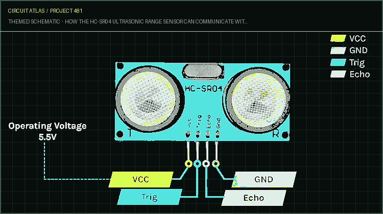
able to construct a wide variety of fascinating projects by combining an Arduino and a PIC microcontroller with this HC-SR04 board. The Pinout of the HC-SR04 Ultrasonic Sensor VCC, Trig, Echo, and Gnd are the names of the module's four available pins on the HC-SR04 ultrasonic proximity sensor. Because both the input and output of this sensor are digital, we need to connect it to the microcontroller's digital pin in order to use it. The HC-pinout SR04's is shown in the following image. VCC - The supply pin of the HC-SR04 Module. Establish a connection between it and the ESP32's 5V pin. Trig - This is the trigger pin of the HC-SR04 module. An ultrasonic burst can be triggered from the sensor by setting this pin to HIGH for ten microseconds. Echo - This is the HC-SR04 sensor module's echo pin. This pin holds its high state until either the sensor receives the echo back or a predetermined amount of time has elapsed.
GND - This is the module's Ground pin; join it to the ESP32's Ground pin. HC-SR04 Ultrasonic Sensor Overview Before we move on to figuring out how the ultrasonic distance sensor operates, let's first get a better understanding of what ultrasound is: Ultrasound is a type of high-pitched sound wave in which the frequency of the wave is higher than what is audible to humans due to the human ear's limited range. The audible range for humans is between 20 Hz and 20 kHz; however, the sound that is emitted from the module is significantly higher in frequency than what human ears are able to process, and as a result, it is inaudible to humans. Two ultrasonic transducers are used in the construction of an ultrasonic distance sensor. One of these transducers has a frequency of 40 kilohertz and functions as a transmitter, while the other functions as a receiver and listens to the reflected received pulses. The output pulse that the sensor generates is in a manner that is proportional to the distance between it and the object that is being sensed. The sensor has an operating voltage of 5 volts and can provide excellent non-contact range detection between 2 cm and 400 cm. The distance of the object can be determined by reading the pulse width with a microcontroller, and this can be done to determine how far away the object is. The ultrasonic sensor can be interfaced with any microcontroller; if you follow the link, you will find information on all of the possible interfaces for the ultrasonic sensor. What is the operation of the HC-SR04 Ultrasonic Distance Sensor? In order to get the process of measuring distance started, we need to set the trigger pin to high for ten microseconds. As a response, the sensor sends out an ultrasonic burst consisting of eight pulses at a frequency of forty
kilohertz. The eighth pulse is constructed in such a way that it enables the receiver to differentiate between the transmitted pulse and the background ultrasound. When the process of sending 8 pulses is complete, the echo pin will go high, which will indicate that the return signal has been received. In the event that those transmitted signals do not return after 38 milliseconds, this indicates that there is no obstruction in the path of the sensor. If those pulses are reflected back, the echo pin will go low as soon as the signal is received. This will cause a pulse to be generated on the echo pin, the width of which will range anywhere from 150 microseconds to 25 milliseconds, depending on how long it took to receive the signal.
Calculating the Distance by measuring the pulse width We can use the equation for distance, speed, and time in conjunction with the received pulse width to calculate the distance from the reflected object. This can be done by using the received pulse width. Let's assume that we have no idea how far X is from us, but that we have measured a pulse width of 700 microseconds on the echo pin. Following is the formula that will be used by us now when figuring out the distance. Distance = Speed x Time We now know that the speed of sound is 343.2 meters per second. We need to convert the speed of sound to cm/uS, which comes out to 0.03432 cm/uS, so that we can calculate the distance. In addition to this, we need to know the time value that was received from the ultrasonic sensor, which is 700 uS. Distance = (0.03432 cm/us x 700uS) / 2 = 12.012 cm
The distance between the object and the sensor is now known to be 12.012 centimeters. Ultrasonic range sensor module HC-SR04: Frequently Asked Questions Q. What is the upper limit of the HC-range? SR04's The HC-SR04 has a maximum range of 400 centimeters, which is equivalent to 13 feet. Q. Can HC SR04 detect water? Yes, this sensor is able to determine the height of the water's surface, and this information can serve as an early warning of an impending flood. There are a lot of projects that involve water surface-level detection systems that are available on the internet. These systems make use of ultrasonic sensors and the ESP8266-12E module. Q. Is the ultrasonic sensor HC-SR04 waterproof? The HC-SR04 module is extremely delicate; it is susceptible to damage from dust and can even be blown apart by strong winds; moreover, it is not waterproof. However, there are specific modules that can withstand high levels of humidity and can be purchased on the market today. These modules were developed with some level of water resistance built into their designs. Q. Does HC SR04 work with 3.3 V? The datasheet indicates that it cannot be powered by 3.3V, but there is a workaround: you can use 3.3V to trigger the module, and then in the echo line, you can use a voltage divider to reduce the voltage to 3.3V using an appropriate one. ESP32 with HC-SR04 Ultrasonic Sensor Circuit Diagram
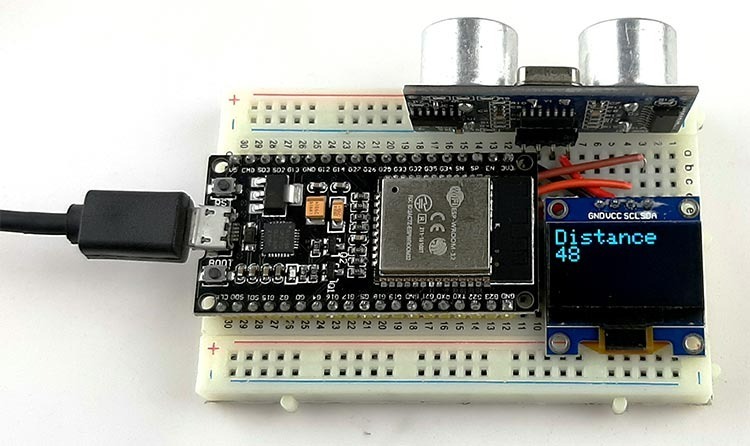
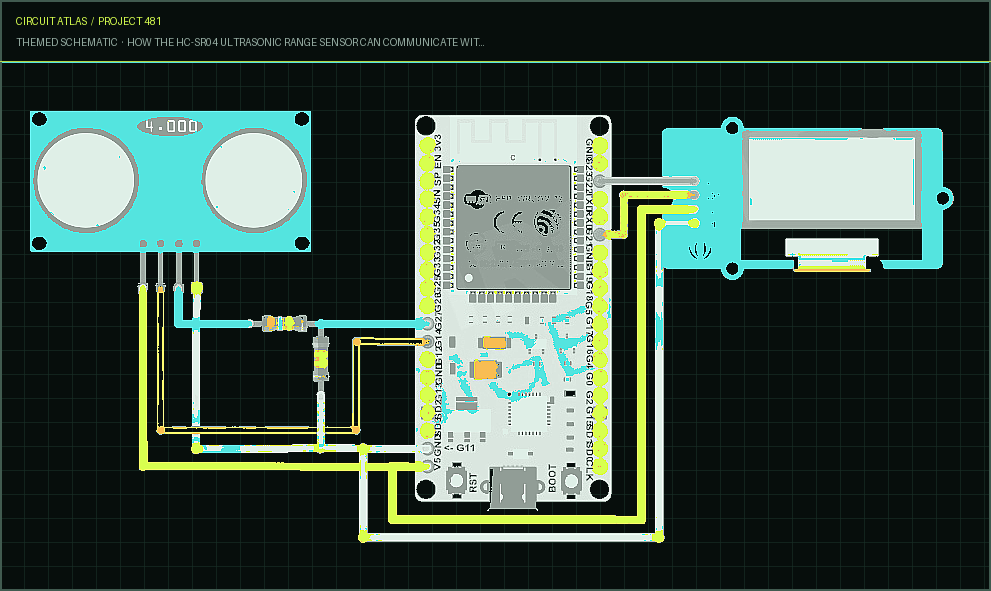
Now that we have a comprehensive understanding of how the HC-SR04 ultrasonic module operates, we have connected all of the required wires to the ESP32 module. Next, we will write a straightforward code in order to test the module and ensure that it is functioning properly. The illustration below shows the full test schematic for connecting the ESP32 to the HC-SR04 sensor. The HC-SR04 module and an OLED module have been connected to the ESP32, as can be seen in the image that is located above this one. Because the ultrasonic module requires 5V to function, the procedure for connecting it is very straightforward. Because of this, we have implemented a voltage divider in the echo pin in order to reduce the 5V output to 3.3V. For the HC- SR04 module, any digital pin of the ESP32 can be used as an I/O; however, for the OLED model, you need to use the I2C pin, which is the IO21 and IO22 of the ESP32 module. You can use any digital pin of the ESP32 for the HC-SR04 module. The procedure for making the connection is now complete; the image of the hardware that can be found below will provide you with a clearer picture of how the circuit is connected.
How to Use Arduino Code to Connect HC-SR04 Sensor to ESP32 In the following section of this article, we will be describing the code that will be utilized to measure the distance with the HC SR04 sensor and display the results on the 128X64 display. However, before we begin the process of writing code, we will need to install the Adafruit GFX library, the Adafruit SSD1306.h library, and the NewPing.h library from the library manager of Arduino in order to process the data coming from the sensor and display. When we first begin work on our code, we begin by including all of the necessary libraries. These libraries include the Adafruit GFX library as well as the NewPing library. Since the SPI library and the Wre library are dependencies of the Adafruit GFX library, we need to include those two libraries first before we can include the Adafruit GFX library. How to Fix Issues with the HC-SR04 Ultrasonic Sensor Module If you are having issues connecting the HC-SR04 to the ESP32, the first thing you need to do is check the power line. If you try to power the ultrasonic sensor module with 3.3V instead of 5V, the module will be unstable. The module was designed to work with a supply of 5V. If you are working with a library that is not supported by your module, the module may provide you with inaccurate information. Therefore, you need to check the library that you have installed or you need to install the appropriate library for the module. If the module is still not functioning properly, you might want to examine it alongside another module.
You built How the HC-SR04 Ultrasonic Range Sensor Can Communicate with the ESP32.
You followed the full workflow from understanding the mission to testing the finished project. That is a real engineering achievement - well done.
How does a Servo Motor Work and How to Interface it with ESP32?
Ready to reuse what you learned in another project from the same track?
Start this project →