PC Based Candle Igniter
Here is a PC-based candle-igniter system that lets you light a candle with matchsticks by pressing the "Enter" key on the PC's keyboard. It is especially helpful for special events like b…
Know the mission before touching a wire.
Understand what you are making, prepare the right tools, and make the workbench safe.
Project details
PC Based Candle Igniter is a electronics project. Here is a PC-based candle-igniter system that lets you light a candle with matchsticks by pressing the "Enter" key on the PC's keyboard. It is especially helpful for special events like b…
- Source pages
- 469-471
- Named parts
- 2
- Build goal
- Working, tested prototype
Tools you need
- Digital multimeter
- Wire stripper and side cutters
- Soldering iron with a fine tip
- Current-limited bench supply
Use eye protection, good lighting, and a clean insulated surface throughout the build.
Safety precautions
- Disconnect every power source before changing a connection.
- Check component polarity, pinout, and supply voltage twice.
- Use a current limit for the first power-up.
- This project may involve hazardous voltage. Work only with qualified supervision and proper isolation.
Gather, identify, and understand every part.
Use the standardized inventory, then open What's this? to learn each part's role, advantages, limitations, handling, and specifications.
What's this?Image, role, pros, cons, handling & specifications
 SEMICONDUCTOR LEARNING VIEW
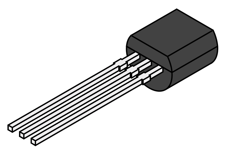
BC548
A semiconductor stage performs switching, amplification, regulation, rectification, or logic.
What it does hereIt controls current or signal flow at a defined point in the circuit.
Buy / compare this part ↗Advantages
- Fast and efficient
- Compact
- Can control larger loads from smaller signals
Limitations
- Pin order varies
- Sensitive to overvoltage and reverse polarity
- May need cooling or bias components
Handling
- Verify the datasheet pinout
- Avoid static and soldering heat
- Check notch, stripe, or flat-face orientation
Specifications to verify
- Use the exact model, value, package, and rating listed for BC548; similar-looking parts are not always interchangeable.
- Confirm pinout, maximum voltage/current, dissipation, gain or forward voltage, and package.
What's this?Image, role, pros, cons, handling & specifications
T1, T2 - transistor stages identified in the circuit
A semiconductor stage performs switching, amplification, regulation, rectification, or logic.
What it does hereIt controls current or signal flow at a defined point in the circuit.
Buy / compare this part ↗Advantages
- Fast and efficient
- Compact
- Can control larger loads from smaller signals
Limitations
- Pin order varies
- Sensitive to overvoltage and reverse polarity
- May need cooling or bias components
Handling
- Verify the datasheet pinout
- Avoid static and soldering heat
- Check notch, stripe, or flat-face orientation
Specifications to verify
- Use the exact model, value, package, and rating listed for T1, T2 - transistor stages identified in the circuit; similar-looking parts are not always interchangeable.
- Confirm pinout, maximum voltage/current, dissipation, gain or forward voltage, and package.
Connect one verified path at a time.
Explore the named components and standardized signal flow, then use Source Check to verify exact physical pins, values, and topology before applying power.
Trace this circuit.
PC Based Candle Igniter: interactive parts, standardized terminals, responsive anchored wires, student explanations, and the original circuit reference in one shared system.
Trace before wiring
Follow power, ground, inputs, processing, and outputs in that order. Never guess a pin from package shape alone.
Connect with power off
Make short, labelled connections and share a common ground only where the schematic requires it.
Inspect every joint
Check continuity, polarity, adjacent shorts, and loose connections before the first power-up.
Open all source diagrams and build views 2 visuals
Confirm the hardware-only control path.
This project does not include firmware in the source. The circuit itself provides the required behaviour.
How to connect
- Match every controller label to the circuit view and source pin map.
- Join grounds before signal wires when separate low-voltage supplies are used.
- Keep motors, relays, pumps, and other loads on a suitable driver and external supply.
Common mistakes
Reversed VCC/GND, board-label versus GPIO-number confusion, missing common ground, and charge-only USB cables.
Troubleshoot
Disconnect loads, continuity-test one path at a time, then test with a current limit.
Software preparation
No IDE, board package, library, or firmware upload is required for this project.
If you add a programmable controller as an extension, document its pin map separately.
How to upload code
The original design is implemented entirely in hardware, so proceed after verifying the circuit and supply.
Assemble, deploy, test, and troubleshoot.
Use the complete source notes in build order, then pass the final checks before calling the project finished.
Build in functional stages
- Power and regulation
- Controller or processing stage
- Inputs and sensors
- Outputs and loads
- Enclosure and strain relief
Power up safely
- Inspect unpowered continuity first
- Apply the lowest safe current limit
- Measure supply rails before signals
- Add one load at a time
- Record expected and actual results
Work from simple to complex
- Confirm power, ground, polarity, and orientation
- Compare each pin with the source
- Test inputs separately from outputs
- Replace only one variable at a time
- Power off before every correction
Follow the documented instructions.
These notes come from this project's source and remain in their original order.
Project overview
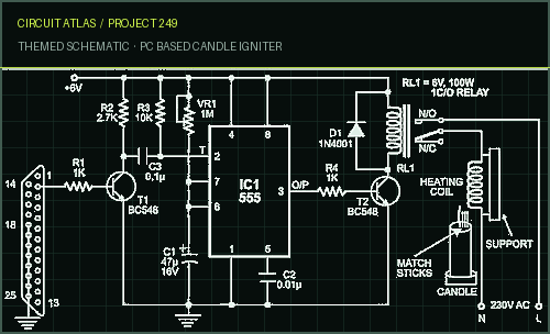
Project build noteHere is a PC-based candle-igniter system that lets you light a candle with matchsticks by pressing the "Enter" key on the PC's keyboard. It is especially helpful for special events like birthdays and anniversaries. As shown in the figure, the number of matchsticks needed to light the candle are placed along its wick. The heating coil that is used to light the matchsticks is kept close by. For the candle-matchsticks setup, the circuitry between the PC and the heating coil is made up of an inverter, a monostable, and a relay driver. The inverter is the transistor BC548 (T1), the monostable circuit is the IC 555 (IC1), and the relay driver is the transistor SL100 (T2).
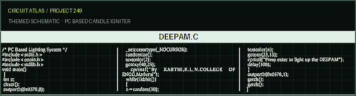
PC Based Candle Igniter Circuit When you press the "Enter" key on the keyboard, the inverted output at the collector of transistor T1 goes low, triggering IC1 through its pin 2. The monostable's output pin 3 goes high, and transistor T2 works for about 50 seconds. When transistor T2 is turned on, relay RL1 is turned on. The normally open (N/O) contact on relay RL1 then connects the heating coil to 230V AC. You can also use an electric cigarette lighter instead of the heating coil. When the heating coil is connected to the 230V AC, it gets very hot and lights the matchsticks. The matchsticks' flames light the candle. Software The program is simple and easy to understand because it was written in the "C" language. The data is sent to the interfacing circuitry through the
parallel port D-type female connector that is usually on the back of the PC. The program uses the address 378H of parallel port LPT1. The control signal to turn on the relay comes from the parallel port pin 2 that corresponds to data bit D0. This turns on the relay, which then connects the load to the AC mains. This circuit only uses one output from the PC's parallel port to light the candle, but it can be expanded to light up to eight diyas (candles) in South India by using eight outputs, making a small change to the program, and adding seven more similar circuits.
You built PC Based Candle Igniter.
You followed the full workflow from understanding the mission to testing the finished project. That is a real engineering achievement - well done.
Sound Operated Intruder Alarm
Ready to reuse what you learned in another project from the same track?
Start this project →