Designing a Smartwatch using ESP32 - Magnetometer and Gyroscope
Gyroscope We have looked at how to interface the BH1750 ambient light sensor and the MAX30102 Heart rate sensor for our smartwatch project in the previous part, which was titled Designing…
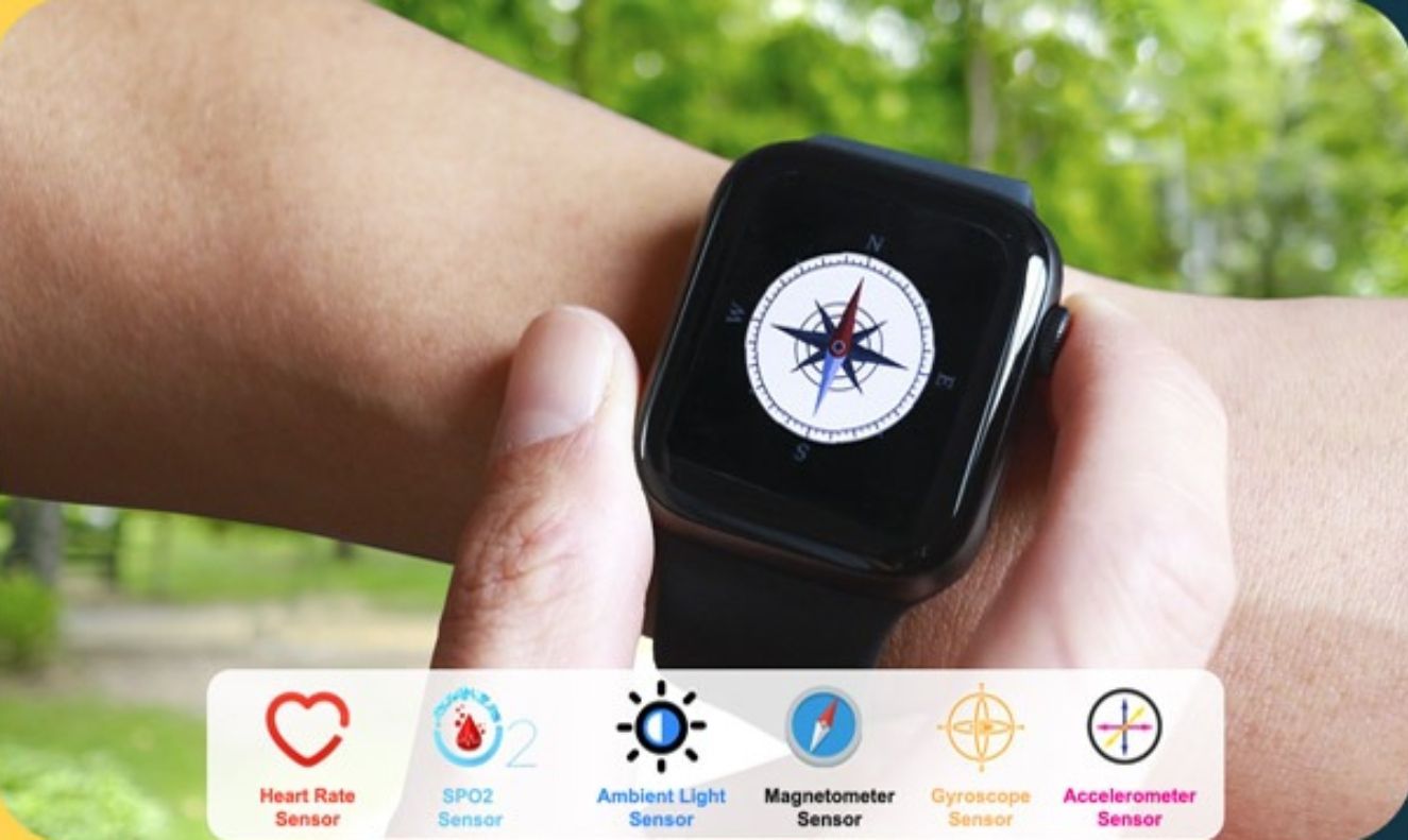
Know the mission before touching a wire.
Understand what you are making, prepare the right tools, and make the workbench safe.
Project details
Designing a Smartwatch using ESP32 - Magnetometer and Gyroscope is a iot project. Gyroscope We have looked at how to interface the BH1750 ambient light sensor and the MAX30102 Heart rate sensor for our smartwatch project in the previous part, which was titled Designing…
- Source pages
- 1337-1346
- Named parts
- 4
- Build goal
- Working, tested prototype
Tools you need
- Digital multimeter
- Wire stripper and side cutters
- Soldering iron with a fine tip
- Current-limited bench supply
- Computer with a data-capable USB cable
Use eye protection, good lighting, and a clean insulated surface throughout the build.
Safety precautions
- Disconnect every power source before changing a connection.
- Check component polarity, pinout, and supply voltage twice.
- Use a current limit for the first power-up.
- Keep liquids, loose metal, and uninsulated wires away from the bench.
Gather, identify, and understand every part.
Use the standardized inventory, then open What's this? to learn each part's role, advantages, limitations, handling, and specifications.
What's this?Image, role, pros, cons, handling & specifications
ESP32
A programmable controller that reads inputs, makes decisions, and drives the project's outputs.
What it does hereIt is the control centre and must use the documented board, pin map, supply, and logic level.
Buy / compare this part ↗Advantages
- Reprogrammable and reusable
- Large learning ecosystem
- Complex behaviour remains changeable
Limitations
- GPIO voltage and current are limited
- Some pins affect boot or communication
- Loads normally need a driver
Handling
- Disconnect power before rewiring
- Avoid static discharge
- Never power motors, relays, or pumps directly from GPIO
Specifications to verify
- Use the exact model, value, package, and rating listed for ESP32; similar-looking parts are not always interchangeable.
- Confirm operating voltage, logic level, pinout, memory, USB interface, and maximum GPIO current.
What's this?Image, role, pros, cons, handling & specifications
Heart rate sensor
A sensor converts a physical condition into an electrical signal the circuit can measure.
What it does hereIt provides project input as an analogue, digital, resistive, frequency, or calibrated signal.
Buy / compare this part ↗Advantages
- Adds real-world awareness
- Can usually be tested independently
- Often supports calibration
Limitations
- Readings can drift
- Placement affects results
- Some sensors need warm-up or calibration
Handling
- Protect the sensing surface
- Observe supply voltage and polarity
- Keep signal leads away from noisy power wiring
Specifications to verify
- Use the exact model, value, package, and rating listed for Heart rate sensor; similar-looking parts are not always interchangeable.
- Confirm supply range, output type, measurement range, accuracy, response time, and pin order.
What's this?Image, role, pros, cons, handling & specifications
MAX30102
A named project component whose exact role is defined by the source circuit and build guide.
What it does hereIt performs a documented electrical, control, interface, or construction function in this project.
Buy / compare this part ↗Advantages
- Selected for this project
- Can be checked independently
- Supports modular troubleshooting
Limitations
- Substitutes may differ
- Generic names can hide variants
- Pinouts and ratings vary
Handling
- Compare the received part with the source
- Keep it labelled
- Do not force connectors or adjusters
Specifications to verify
- Use the exact model, value, package, and rating listed for MAX30102; similar-looking parts are not always interchangeable.
- Confirm dimensions, ratings, connection method, polarity, and environmental limits.
What's this?Image, role, pros, cons, handling & specifications
MPU6050
A sensor converts a physical condition into an electrical signal the circuit can measure.
What it does hereIt provides project input as an analogue, digital, resistive, frequency, or calibrated signal.
Buy / compare this part ↗Advantages
- Adds real-world awareness
- Can usually be tested independently
- Often supports calibration
Limitations
- Readings can drift
- Placement affects results
- Some sensors need warm-up or calibration
Handling
- Protect the sensing surface
- Observe supply voltage and polarity
- Keep signal leads away from noisy power wiring
Specifications to verify
- Use the exact model, value, package, and rating listed for MPU6050; similar-looking parts are not always interchangeable.
- Confirm supply range, output type, measurement range, accuracy, response time, and pin order.
Connect one verified path at a time.
Explore the named components and standardized signal flow, then use Source Check to verify exact physical pins, values, and topology before applying power.
Trace this circuit.
Designing a Smartwatch using ESP32 - Magnetometer and Gyroscope: interactive parts, standardized terminals, responsive anchored wires, student explanations, and the original circuit reference in one shared system.
Trace before wiring
Follow power, ground, inputs, processing, and outputs in that order. Never guess a pin from package shape alone.
Connect with power off
Make short, labelled connections and share a common ground only where the schematic requires it.
Inspect every joint
Check continuity, polarity, adjacent shorts, and loose connections before the first power-up.
Open all source diagrams and build views 6 visuals
Confirm the hardware-only control path.
This project does not include firmware in the source. The circuit itself provides the required behaviour.
How to connect
- Match every controller label to the circuit view and source pin map.
- Join grounds before signal wires when separate low-voltage supplies are used.
- Keep motors, relays, pumps, and other loads on a suitable driver and external supply.
Common mistakes
Reversed VCC/GND, board-label versus GPIO-number confusion, missing common ground, and charge-only USB cables.
Troubleshoot
Disconnect loads, continuity-test one path at a time, then test with a current limit.
Software preparation
No IDE, board package, library, or firmware upload is required for this project.
If you add a programmable controller as an extension, document its pin map separately.
How to upload code
The original design is implemented entirely in hardware, so proceed after verifying the circuit and supply.
Assemble, deploy, test, and troubleshoot.
Use the complete source notes in build order, then pass the final checks before calling the project finished.
Build in functional stages
- Power and regulation
- Controller or processing stage
- Inputs and sensors
- Outputs and loads
- Enclosure and strain relief
Power up safely
- Inspect unpowered continuity first
- Apply the lowest safe current limit
- Measure supply rails before signals
- Add one load at a time
- Record expected and actual results
Work from simple to complex
- Confirm power, ground, polarity, and orientation
- Compare each pin with the source
- Test inputs separately from outputs
- Replace only one variable at a time
- Power off before every correction
Follow the documented instructions.
These notes come from this project's source and remain in their original order.
Project overview
Project build noteGyroscope We have looked at how to interface the BH1750 ambient light sensor and the MAX30102 Heart rate sensor for our smartwatch project in the previous part, which was titled Designing Smartwatch Using ESP32. This part was split into two parts. In this section, we will discuss the different types of sensors that can be interfaced with our smartwatch and how to do so. The HMC5883L/QMC5883L Magnetometer sensor and the MPU6050 accelerometer gyroscope sensor are going to be interfaced in this section. We are going to examine the process of interfacing each of these modules independently. Prerequisites - Installing Necessary Libraries The GitHub repository that is linked to at the bottom of the article contains all of the necessary library files. You will need to download them and then extract them into the library folder that is located inside of the Arduino
document folder. You can skip the step before this one if you have already installed the necessary components, but you will still need to install the display library. You are required to use the TFT eSPI library that I have attached for the display. When that is finished, let's move on to the next step, which is the interface. Required Libraries 1. TFT_eSPI Library (Modified) 2. QMC5883L Library from DFRobots Interfacing Magnetic Sensor The HMC5883L/QMC5883L is going to be the component that we use for the magnetic sensor. We can make use of the sensor as a digital compass given that it is able to indicate the geographic directions of north, south, east, and west. Inside of the HMC5883L/QMC5883L are three different magneto-resistive materials that are organized along the axes of x, y, and z. The strength of the earth's magnetic field has an effect on the amount of electric current that flows through these materials. Therefore, we are able to detect shifts in the magnetic field of the Earth by monitoring the change in the current that is flowing through these materials. After the change in the magnetic field has been absorbed, the values can then be sent to any embedded controller using the I2C protocol. Examples of embedded controllers include a microcontroller and a processor. HMC5883L/QMC5883L Module Pinout
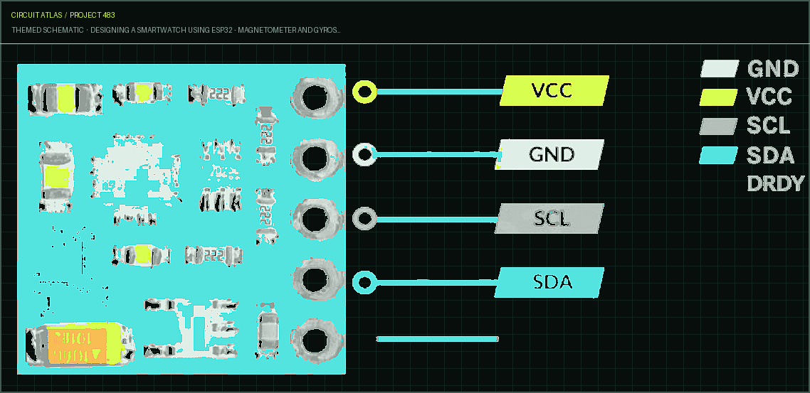
A total of five pins are present on the HMC5883L/QMC5883L module. With the exception of the VCC and Ground pins, all of the pins on this sensor module are digital. There is one optional interrupt pin in addition to the four pins that are used for interfacing with the MCU. The HMC5883L/QMC5883L module has the following pinout, as specified by
the manufacturer
Project build noteGND - Ground connection for the module. Establish a connection to the ESP32's GND pin. VCC - Provides power for the module. Establish a connection to the ESP32's 3.3V pin. SCL - stands for Serial Clock. Utilized for the purpose of providing the clock pulse for I2C Communication. SDA - Serial Data pin. Used for moving data between devices using the I2C communication protocol. DRDY - An interrupt is generated in this pin whenever the output value of the sensor is ready to be read. By default, the module has a pull-up resistor connected to this pin. The value of the output pin is set to "0" for a period of 250 microseconds when the module's output value is ready. Circuit to Interface a Magnetic sensor with an ESP32
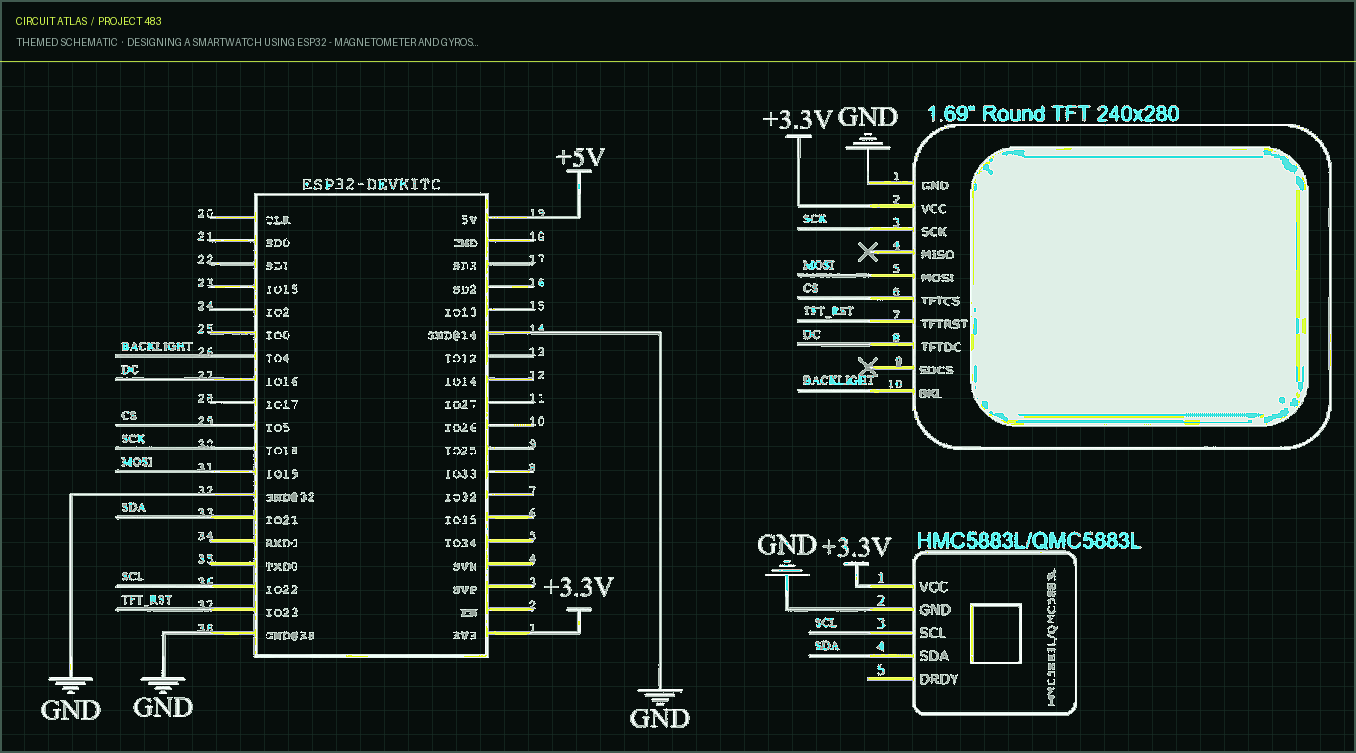
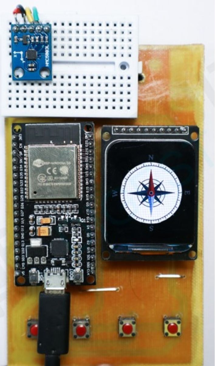
When conducting tests, ensure that the Magnetic sensor module and the display module are connected to the ESP32 Devkit in accordance with the circuit diagram that can be found below. As you did in the previous step, connect the display to the SPI bus and the sensor to the I2C line. The actual configuration can be seen here. I2C lines are used to make the connection between the ESP32 and the QMC5883L module. Testing Sensor The QMC5883L demo code and any necessary libraries can be obtained from GitHub once all of the connections have been completed in accordance with the schematics. The libraries should be extracted into the Arduino library folder, while the code should be extracted into any folder, and then opened in the Arduino IDE. Compile the code after selecting "ESP32 Devkit" as the board to use. After the code has been compiled, it can then be uploaded to the ESP32.
Figure: Prototype of Magnetic sensor with an ESP32
Project build noteOn the display will be a digital representation of a compass. You can see that the compass is pointing in the right direction, and it will continue to do so so long as there is no magnetic interference. You can verify this by looking at it. Make sure there aren't any magnetic materials or magnetic fields in the area around the sensor while you're testing it. In that case, it might have an effect on the readings. Code explanation Both the TFT eSPI and DFRobot QMC5883 libraries were incorporated into the code by our team. The HMC5883L and QMC5883L chip families
are both supported by the DFRobot QMC5883 library. After we have finished initializing the library, we will set the appropriate configuration based on the chip address that we have been given. This is necessary due to the fact that both of these sensors have distinctive I2C addresses and distinct internal register mappings. When it is finished, we will read the register that corresponds to the reading from each axis, and then we will compute the heading based on that information. Adjusting the declination angle to account for our location is necessary in order to carry out an accurate calculation. You can look in the code itself to find the instructions for doing the same thing. After the bearing has been determined, the image of the compass dial will be loaded into the sprite that was previously created in the memory. The sprite is then angledly pushed onto the display after it has been rotated. In order to accomplish this, we have made use of the pushRotated function that is located within the TFT eSPI library. Because of this function, the image that is being sent to the display will be rotated so that it corresponds with the angle that was determined using the QMC5883L. By doing this, our display will be clear and we will have an accurate digital compass that is pointing to the north. In order to achieve precise results, it is essential to secure the sensor in the appropriate orientation and keep it away from any magnetic substances. It is important to keep in mind that even the breadboard's contacts can have an effect on the sensor. Interfacing Accelerometer Gyroscope sensor We went with the reliable and widely used MPU6050 sensor for the accelerometer and gyroscope sensor. The fact that it is both inexpensive and simple to work with contributes to the DIY community's widespread adoption of the product. This sensor will be utilized by us for the purpose of
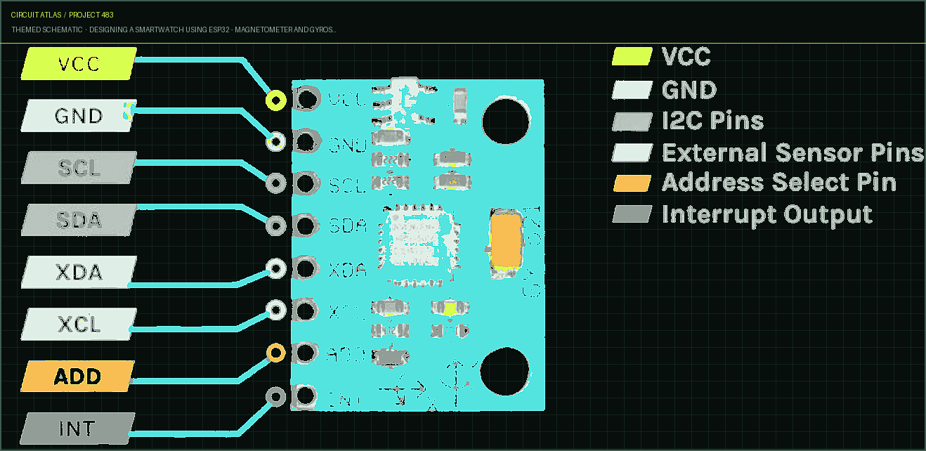
detecting motion and enabling features such as rise to wake up. First, let's take a look at the sensor's individual technical specifications. The MPU6050 is a widely used accelerometer and gyroscope chip that has a measurement resolution of 16 bits and features six axes of sensing capability. Due to the low price and the high accuracy in sense, it has gained a lot of popularity in the do-it-yourself community. Even a large number of commercial products have the MPU6050 embedded in them. Inertial measurement units, also known simply as IMUs, are typically comprised of gyroscopes and accelerometers. IMU sensors are utilized in a huge selection of applications, including mobile phones, tablets, satellites, spacecraft, drones, unmanned aerial vehicles (UAVs), robotics, and many others. Motion tracking, detection of orientation and position, flight control, and other applications all make use of them. MPU6050 Module Pinout A total of 8 pins can be found on the MPU6050 module. where the interfacing requires a minimum of four pins in order to function properly. The following is a list of the pinouts on the MPU6050 module:
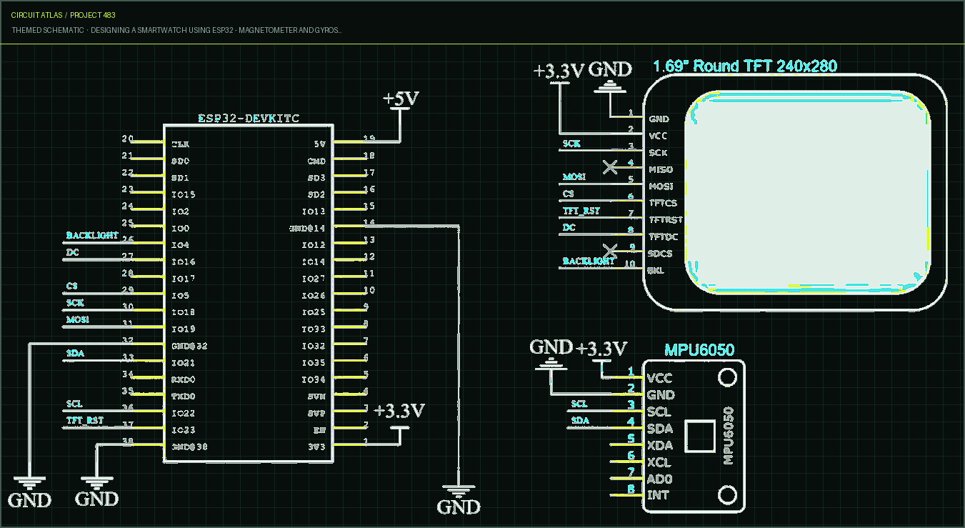
GND - Module's ground connection. Establish a connection to the ESP32's GND pin. VCC - supplies power to the module. Establish a connection to the ESP32's 3.3V pin. SCL - stands for Serial Clock. Utilized for the purpose of providing the clock pulse for I2C Communication. SDA Serial Data pin. Used for moving data between devices using the I2C communication protocol. XDA - Auxiliary Serial Data - Can be used to connect MPU6050 with other I2C modules. XCL - Auxiliary Serial Clock: This can be used to connect MPU6050 to other I2C modules. ADD/AD0 - Address select pin in the event that more than one MPU6050 module is being utilized. INT - Interrupt pin used to indicate to MCU that data is ready to be read. Circuit Diagram for the ESP32 and Accelerometer/Gyroscope Sensor Connect the accelerometer gyroscope sensor module and the display module to the ESP32 Devkit in accordance with the circuit diagram that can be found below. This will allow you to test the device. As you did in the previous step, connect the display to the SPI bus and the sensor to the I2C line.
The actual configuration can be seen here. In order to have the freedom to move the module around while the test is being performed, the MPU6050 module is connected using a jumper cable. Testing Sensor When you have finished making all of the connections in accordance with the schematics, go to GitHub and download the MPU6050 demo code. It should then be opened in the Arduino IDE after being extracted to a folder. Compile the code after selecting "ESP32 Devkit" as the board to use. After the code has been compiled, it can then be uploaded to the ESP32. The display will depict a cube in three dimensions. The cube can be rotated by rotating the MPU6050 module in its center. The gyroscope data will be read from the MPU6050 by the ESP32, and the 3D cube will be processed according to those values. Code Explanations Within the code, we have produced a three-dimensional cube that is comprised of a total of twelve lines. The reading from the gyroscope sensor
will determine the direction that the cube will rotate in. The cube can be rotated by rotating the MPU6050 module in its center. The gyroscope data will be read from the MPU6050 by the ESP32, and then the data will be processed in order to calculate the coordinates of each line that is used to create the 3D. We have not made use of any particular library in order to read the values that are stored in the MPU6050. Instead, we read those values directly from the MPU6050 registers using the I2C Wire. Read function. These values were retrieved from the MPU6050. We are going to read a total of 14 registers, each of which will contain the x, y, and z data that was generated by the accelerometer and gyroscope.
You built Designing a Smartwatch using ESP32 - Magnetometer and Gyroscope.
You followed the full workflow from understanding the mission to testing the finished project. That is a real engineering achievement - well done.
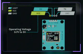
How Does a NEO-6M GPS Module Work and How to Interface it with ESP32
Ready to reuse what you learned in another project from the same track?
Start this project →