IoT Based Electricity Energy Meter using ESP32 & Blynk
In this project, we will discover how to construct our very own Internet of Things–based electricity energy meter utilizing ESP32 and how to monitor data on the Blynk application. In the…
Know the mission before touching a wire.
Understand what you are making, prepare the right tools, and make the workbench safe.
Project details
IoT Based Electricity Energy Meter using ESP32 & Blynk is a iot project. In this project, we will discover how to construct our very own Internet of Things–based electricity energy meter utilizing ESP32 and how to monitor data on the Blynk application. In the…
- Source pages
- 1433-1442
- Named parts
- 9
- Build goal
- Working, tested prototype
Tools you need
- Digital multimeter
- Wire stripper and side cutters
- Soldering iron with a fine tip
- Current-limited bench supply
- Computer with a data-capable USB cable
Use eye protection, good lighting, and a clean insulated surface throughout the build.
Safety precautions
- Disconnect every power source before changing a connection.
- Check component polarity, pinout, and supply voltage twice.
- Use a current limit for the first power-up.
- This project may involve hazardous voltage. Work only with qualified supervision and proper isolation.
Gather, identify, and understand every part.
Use the standardized inventory, then open What's this? to learn each part's role, advantages, limitations, handling, and specifications.
What's this?Image, role, pros, cons, handling & specifications
ESP32 WiFi Module
A programmable controller that reads inputs, makes decisions, and drives the project's outputs.
What it does hereIt is the control centre and must use the documented board, pin map, supply, and logic level.
Buy / compare this part ↗Advantages
- Reprogrammable and reusable
- Large learning ecosystem
- Complex behaviour remains changeable
Limitations
- GPIO voltage and current are limited
- Some pins affect boot or communication
- Loads normally need a driver
Handling
- Disconnect power before rewiring
- Avoid static discharge
- Never power motors, relays, or pumps directly from GPIO
Specifications to verify
- Use the exact model, value, package, and rating listed for ESP32 WiFi Module; similar-looking parts are not always interchangeable.
- Confirm operating voltage, logic level, pinout, memory, USB interface, and maximum GPIO current.
What's this?Image, role, pros, cons, handling & specifications
ZMPT101B AC Voltage Sensor Module
A sensor converts a physical condition into an electrical signal the circuit can measure.
What it does hereIt provides project input as an analogue, digital, resistive, frequency, or calibrated signal.
Buy / compare this part ↗Advantages
- Adds real-world awareness
- Can usually be tested independently
- Often supports calibration
Limitations
- Readings can drift
- Placement affects results
- Some sensors need warm-up or calibration
Handling
- Protect the sensing surface
- Observe supply voltage and polarity
- Keep signal leads away from noisy power wiring
Specifications to verify
- Use the exact model, value, package, and rating listed for ZMPT101B AC Voltage Sensor Module; similar-looking parts are not always interchangeable.
- Confirm supply range, output type, measurement range, accuracy, response time, and pin order.
What's this?Image, role, pros, cons, handling & specifications
SCT-013-030 Non-invasive AC Current Sensor
A sensor converts a physical condition into an electrical signal the circuit can measure.
What it does hereIt provides project input as an analogue, digital, resistive, frequency, or calibrated signal.
Buy / compare this part ↗Advantages
- Adds real-world awareness
- Can usually be tested independently
- Often supports calibration
Limitations
- Readings can drift
- Placement affects results
- Some sensors need warm-up or calibration
Handling
- Protect the sensing surface
- Observe supply voltage and polarity
- Keep signal leads away from noisy power wiring
Specifications to verify
- Use the exact model, value, package, and rating listed for SCT-013-030 Non-invasive AC Current Sensor; similar-looking parts are not always interchangeable.
- Confirm supply range, output type, measurement range, accuracy, response time, and pin order.
What's this?Image, role, pros, cons, handling & specifications
x2 LCD Display
An output component turns an electrical control signal into light, sound, motion, switching, or displayed information.
What it does hereIt presents the circuit result or acts on the physical world.
Buy / compare this part ↗Advantages
- Makes system state visible
- Can be tested separately
- Supports clear troubleshooting
Limitations
- Loads may exceed controller current
- Polarity or driver direction can matter
- Inductive loads create voltage spikes
Handling
- Use the documented driver stage
- Check polarity and load current
- Add flyback protection for inductive loads
Specifications to verify
- Use the exact model, value, package, and rating listed for x2 LCD Display; similar-looking parts are not always interchangeable.
- Confirm voltage, current, polarity, interface, driver requirements, and duty cycle.
What's this?Image, role, pros, cons, handling & specifications
 PASSIVE LEARNING VIEW
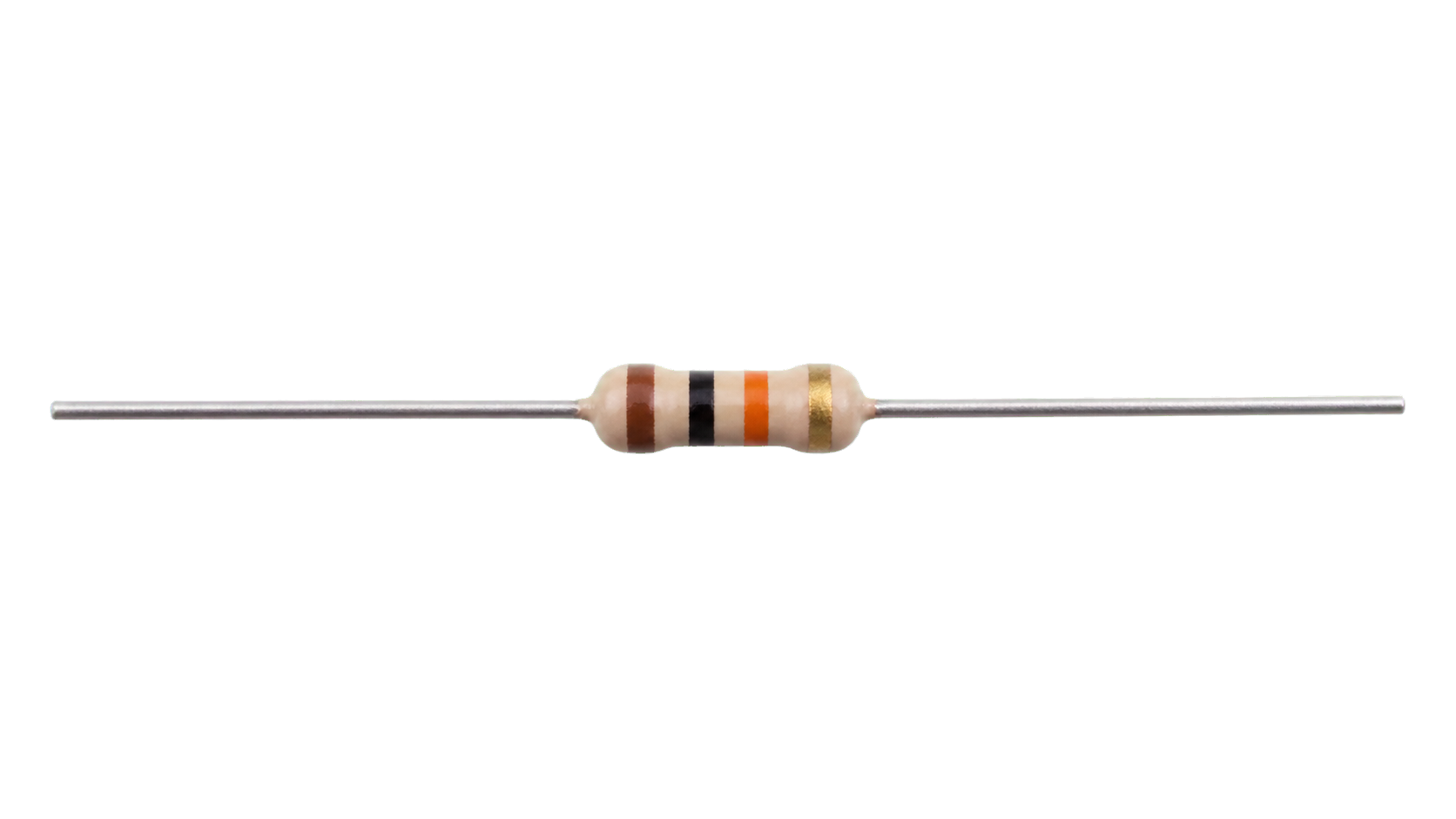
Resistor 10K, Resistor 100ohm
A passive component sets current, voltage, timing, filtering, or signal behaviour without adding gain.
What it does hereIts exact value and tolerance determine how the surrounding stage behaves.
Buy / compare this part ↗Advantages
- Simple and dependable
- Low cost
- Easy to measure before installation
Limitations
- A wrong value can stop or damage the circuit
- Ratings must not be exceeded
- Polarized parts require correct orientation
Handling
- Measure unclear values
- Observe capacitor polarity
- Avoid overheating leads while soldering
Specifications to verify
- Use the exact model, value, package, and rating listed for Resistor 10K, Resistor 100ohm; similar-looking parts are not always interchangeable.
- Confirm value, tolerance, power or voltage rating, polarity, and package size.
What's this?Image, role, pros, cons, handling & specifications
Capacitor 10uF
A passive component sets current, voltage, timing, filtering, or signal behaviour without adding gain.
What it does hereIts exact value and tolerance determine how the surrounding stage behaves.
Buy / compare this part ↗Advantages
- Simple and dependable
- Low cost
- Easy to measure before installation
Limitations
- A wrong value can stop or damage the circuit
- Ratings must not be exceeded
- Polarized parts require correct orientation
Handling
- Measure unclear values
- Observe capacitor polarity
- Avoid overheating leads while soldering
Specifications to verify
- Use the exact model, value, package, and rating listed for Capacitor 10uF; similar-looking parts are not always interchangeable.
- Confirm value, tolerance, power or voltage rating, polarity, and package size.
What's this?Image, role, pros, cons, handling & specifications
Connecting Wires, and Breadboard
A named project component whose exact role is defined by the source circuit and build guide.
What it does hereIt performs a documented electrical, control, interface, or construction function in this project.
Buy / compare this part ↗Advantages
- Selected for this project
- Can be checked independently
- Supports modular troubleshooting
Limitations
- Substitutes may differ
- Generic names can hide variants
- Pinouts and ratings vary
Handling
- Compare the received part with the source
- Keep it labelled
- Do not force connectors or adjusters
Specifications to verify
- Use the exact model, value, package, and rating listed for Connecting Wires, and Breadboard; similar-looking parts are not always interchangeable.
- Confirm dimensions, ratings, connection method, polarity, and environmental limits.
What's this?Image, role, pros, cons, handling & specifications
SCT-013 Current Sensor
A sensor converts a physical condition into an electrical signal the circuit can measure.
What it does hereIt provides project input as an analogue, digital, resistive, frequency, or calibrated signal.
Buy / compare this part ↗Advantages
- Adds real-world awareness
- Can usually be tested independently
- Often supports calibration
Limitations
- Readings can drift
- Placement affects results
- Some sensors need warm-up or calibration
Handling
- Protect the sensing surface
- Observe supply voltage and polarity
- Keep signal leads away from noisy power wiring
Specifications to verify
- Use the exact model, value, package, and rating listed for SCT-013 Current Sensor; similar-looking parts are not always interchangeable.
- Confirm supply range, output type, measurement range, accuracy, response time, and pin order.
What's this?Image, role, pros, cons, handling & specifications
ESP8266 - controller board / IC
A programmable controller that reads inputs, makes decisions, and drives the project's outputs.
What it does hereIt is the control centre and must use the documented board, pin map, supply, and logic level.
Buy / compare this part ↗Advantages
- Reprogrammable and reusable
- Large learning ecosystem
- Complex behaviour remains changeable
Limitations
- GPIO voltage and current are limited
- Some pins affect boot or communication
- Loads normally need a driver
Handling
- Disconnect power before rewiring
- Avoid static discharge
- Never power motors, relays, or pumps directly from GPIO
Specifications to verify
- Use the exact model, value, package, and rating listed for ESP8266 - controller board / IC; similar-looking parts are not always interchangeable.
- Confirm operating voltage, logic level, pinout, memory, USB interface, and maximum GPIO current.
Connect one verified path at a time.
Explore the named components and standardized signal flow, then use Source Check to verify exact physical pins, values, and topology before applying power.
Trace this circuit.
IoT Based Electricity Energy Meter using ESP32 & Blynk: interactive parts, standardized terminals, responsive anchored wires, student explanations, and the original circuit reference in one shared system.
Trace before wiring
Follow power, ground, inputs, processing, and outputs in that order. Never guess a pin from package shape alone.
Connect with power off
Make short, labelled connections and share a common ground only where the schematic requires it.
Inspect every joint
Check continuity, polarity, adjacent shorts, and loose connections before the first power-up.
Open all source diagrams and build views 5 visuals
Confirm the hardware-only control path.
This project does not include firmware in the source. The circuit itself provides the required behaviour.
How to connect
- Match every controller label to the circuit view and source pin map.
- Join grounds before signal wires when separate low-voltage supplies are used.
- Keep motors, relays, pumps, and other loads on a suitable driver and external supply.
Common mistakes
Reversed VCC/GND, board-label versus GPIO-number confusion, missing common ground, and charge-only USB cables.
Troubleshoot
Disconnect loads, continuity-test one path at a time, then test with a current limit.
Software preparation
No IDE, board package, library, or firmware upload is required for this project.
If you add a programmable controller as an extension, document its pin map separately.
How to upload code
The original design is implemented entirely in hardware, so proceed after verifying the circuit and supply.
Assemble, deploy, test, and troubleshoot.
Use the complete source notes in build order, then pass the final checks before calling the project finished.
Build in functional stages
- Power and regulation
- Controller or processing stage
- Inputs and sensors
- Outputs and loads
- Enclosure and strain relief
Power up safely
- Inspect unpowered continuity first
- Apply the lowest safe current limit
- Measure supply rails before signals
- Add one load at a time
- Record expected and actual results
Work from simple to complex
- Confirm power, ground, polarity, and orientation
- Compare each pin with the source
- Test inputs separately from outputs
- Replace only one variable at a time
- Power off before every correction
Follow the documented instructions.
These notes come from this project's source and remain in their original order.
Project overview
Project build noteIn this project, we will discover how to construct our very own Internet of Things–based electricity energy meter utilizing ESP32 and how to monitor data on the Blynk application. In the past, we constructed a GSM Prepaid Energy Meter. Because of the way that technology is now designed, you will need to walk into the meter reading room in order to record any readings. Therefore, keeping an eye on how much electricity you use and recording it can be a time-consuming and laborious chore. The Internet of Things is a useful tool that can help us automate this process. By automating the gathering of remote data, the Internet of Things helps users save both time and money. In recent years, the Smart Energy Meter has been the subject of a significant amount of praise all throughout the world. Why not construct our very own Internet of Things–based electricity and energy meter? It is necessary for us to choose the current sensor in addition to the voltage sensor so that both the current and the voltage can be measured, and therefore so that we can determine the amount of power that has been spent and the total amount of power consumed. The SCT-013 is the most accurate
current sensor that can be purchased anywhere. The SCT-013 Non-Invasive AC Current Sensor Split Core Type Clamp Meter Sensor is a device that can measure AC current of up to 100 amperes and does so without causing any damage to the electrical system. In a similar vein, the AC Voltage Sensor Module ZMPT101B is the most accurate voltage sensor available. The ZMPT101B AC Voltage Sensor performs exceptionally well in situations in which an accurate measurement of AC voltage using a voltage transformer is required. We are able to measure all of the necessary parameters for the Electricity Energy Meter by utilizing the SCT-013 Current Sensor as well as the ZMPT101B Voltage Sensor. Together, the SCT-013 Current Sensor and the ZMPT101B Voltage Sensor will be interfaced with the ESP32 Wifi Module, and then the data will be sent to the Blynk Application. The voltage, current, power, and total unit spent in kWh will all be displayed on the dashboard of the Blynk application.
Component Required
Project build noteESP32 WiFi Module ZMPT101B AC Voltage Sensor Module SCT-013-030 Non-invasive AC Current Sensor 6x2 LCD Display Resistor 10K, Resistor 100ohm Capacitor 10uF Connecting Wires, and Breadboard SCT-013 Current Sensor
The SCT-013 Non-invasive AC Current Sensor Split Core Type Clamp Meter Sensor is capable of measuring AC current of up to 100 amperes and does so without causing any damage to the circuit. Current transformers, often known as CTs, are a type of sensor used to measure alternating current. They are very helpful for assessing the total electricity consumption of a whole building. There is no need to perform any high voltage electrical work in order to attach the SCT-013 current sensors because they can be hooked straight onto either the live or neutral wire. A current transformer is constructed in the same way as any other transformer, with a primary winding, a magnetic core, and a secondary winding. The secondary winding of the transformer is made up of numerous twists of tiny wire that are wrapped around the inside of the casing.
Specifications
Project build note1. 1.Current Input Ranging from 0 to 30 A AC 2. Output Signal: DC 0-1 V 3. Non-linearity, between 2% and 3% 4. The sampling resistance that is built in (RL) is 62 ohms. 5. The ratio of turns is 1800:1. 6. Resistance Grade: Grade B 7. Temperature Range of the Workplace: -25°C to +70°C 8. Dielectric Strength (between the shell and the output): 1000 V AC / 1 mA for 1 minute
ZMPT101B AC Single Phase Voltage Sensor The ZMPT101B AC Single Phase voltage sensor module is based on a high precision ZMPT101B voltage Transformer. This voltage transformer is used to measure the precise AC voltage. When using Arduino or ESP32 to measure alternating current voltage, this is an excellent alternative. The Modules are able to monitor voltage up to a maximum of 250V AC, and the analog output that corresponds to this measurement can be changed. The module is easy to operate and is equipped with a trim potentiometer that has many turns, which may be used to tune and calibrate the ADC output.
Specifications
Project build note1. The ability to test voltages up to 250 volts is present. 2. Conveniently portable and with an integrated high-precision voltage transformer 3. On-board op-amp circuit with a high degree of precision 4. Operating temperature: 40ºC ~ + 70ºC 5. Supply voltage 5 volts to 30 volts Circuit Diagram & Hardware Setup Now let's take a look at the schematic for the Internet of Things-based electricity energy meter that uses ESP32. The schematic for the circuit was created in the software known as Fritzing.
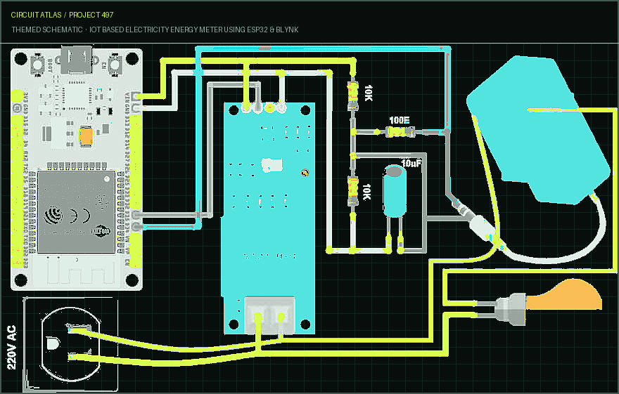
The diagram of the connections is straightforward. Both of the sensors, the SCT-013 Current Sensor and the ZMPT101B Voltage Sensor, have their VCC connections made to the ESP32's Vin supply, which is 5 volts. Both of the modules have a connection made between their GND pins and the GND pin on the ESP32. A connection has been made between the output analog pin of the ZMPT101B Voltage Sensor and the GPIO35 of the ESP32. The output analog pin of the SCT-013 Current Sensor is also wired to the GPIO34 of the ESP32. In addition to a capacitor with a 10 uF rating, you will need two resistors with a value of 10 kilobards and a single resistor with a value of 100 ohms. In addition to the circuit portion, the AC wires that need to have their current and voltage monitored are connected to the input AC Terminal of the Voltage Sensor. In a similar manner, the current sensor clip does not have any connections, and instead, a single live wire or neutral wire is inserted inside the clip component in order to complete the circuit. This is demonstrated in the diagram that was presented before.
It is not necessary to complete this project with a 16x2 LCD. Because we will be watching the ESP32/SCT-013 ZMPT101B/ Energy Meter Data on the Blynk Application, there is no requirement that the LCD be connected. In the event that you want to connect the LCD, you are going to need a great deal of connections. Establish a connection between the pins 4, 6, 11, 12, 13, 14 of the LCD and the ESP32 pins D13, D12, D14, D27, D26, and D25. Additionally, connect the LCD's 1, 5, and 16 Pins to GND, and its 2, 15, and 5 Pins to VCC. To change the contrast of the LCD, connect a potentiometer with a 10K value to Pin 3 of the display.
Setting Up Blynk Application
Project build noteBlynk is an application that can operate any Internet of Things (IoT) based application using a smartphone. It is compatible with both Android and iOS smartphones. It gives you the ability to design your own graphical user interface for an internet of things application. On this page, the data from the IoT Energy Meter will be displayed on the Blynk application. Therefore, go to the Google Play Store and get the Blynk application, then download and install it. Downloads are available in the App Store for users of iOS. After the installation is finished, you may launch the application and register by entering your Email id and Password. Create a new project from the dashboard, and for the platform, choose ESP32 & Wifi Connection. Top 10 Alternatives to Blynk IoT platform Particle. AWS IoT. Fogwing IIoT Platform. Google Cloud IoT Core.
Axonize. IBM Watson IoT Platform. Azure IoT Central. Qt. After that, either use the drag-and-drop functionality or create four widgets, after which you will assign the variable based on the code, and finally you will send the authentication code. The authentication code will be mailed to you at the provided address. Make a copy of this verification code. This information will be incorporated into your code. Required Library Installation 1. EmonLib Library Emonlib Library is where the Electricity Energy Meter gets its information from. Continuous Monitoring of Electricity Energy, often known as EmonLib, performs a series of voltage and current measurements at regular intervals of 5 or 10 seconds. After calculating the accurate average of the voltage and current input channels, EemonLib notifies the sketch that the measurements are ready to be read and processed. These measurements include the voltage and all of the current input channels. 2. Blynk Library Blynk is the most widely used Internet of Things platform for connecting any piece of hardware to the cloud, developing applications to control those devices, and maintaining your products that are already deployed at scale. You can link more than 400 different hardware models to the Blynk Cloud using the Blynk Library, which includes Arduino, ESP8266, and ESP32. Testing: IoT Based Electricity Energy Meter using ESP32 & Blynk
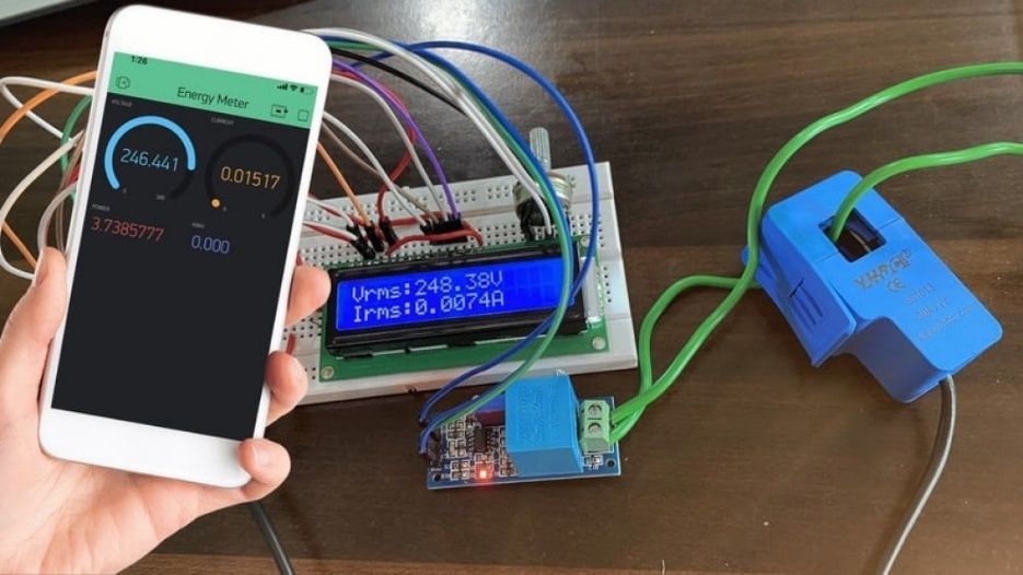
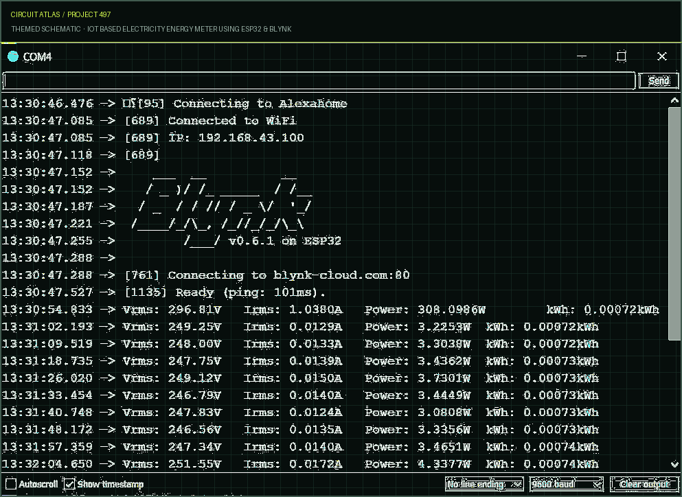
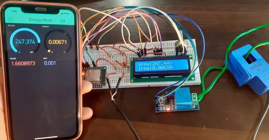
The ESP32 Board will make an attempt to connect to the wifi Network utilizing the SSID and Password that are provided. The following information will appear on the LCD Display when it lights up. Initially. After a pause of five seconds, the data from the energy meter is then uploaded to the Blynk application. Both the Serial Monitor and the Blynk application will display the data for you to view and analyze.
As a result, you are able to keep track of how much electricity your home uses with the help of an Internet of Things-based electricity energy meter.
You built IoT Based Electricity Energy Meter using ESP32 & Blynk.
You followed the full workflow from understanding the mission to testing the finished project. That is a real engineering achievement - well done.
IoT Based Soil Nutrient Monitoring with Arduino & ESP32
Ready to reuse what you learned in another project from the same track?
Start this project →